Size Chart of Cardan Coupling
A cardan coupling, also widely known as a universal joint coupling, is a core mechanical transmission component designed to connect two rotating shafts that present angular, parallel, or axial misalignment in mechanical systems. The size chart of cardan couplings serves as the fundamental technical reference for model selection, installation matching, and operational parameter confirmation in various mechanical transmission scenarios. This standardized dimensional data set covers all key structural and performance-related parameters of different coupling specifications, enabling mechanical engineers and maintenance personnel to quickly screen suitable products according to equipment operating conditions, shaft matching requirements, and installation space constraints. Reasonable utilization of the cardan coupling size chart effectively avoids mismatched installation, insufficient load-bearing capacity, and operational failure risks caused by improper model selection, while maximizing the stability and service life of power transmission systems across light, medium, and heavy-duty mechanical equipment applications.
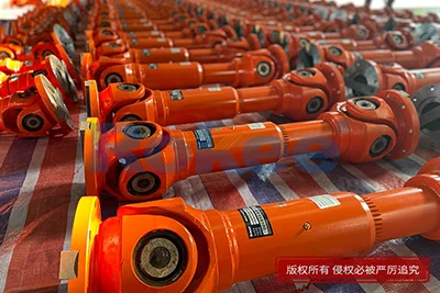
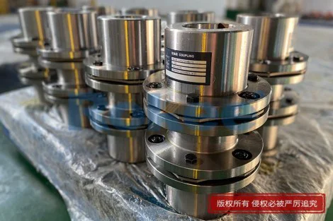
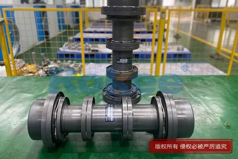
The core composition of a cardan coupling size chart centers on structural dimensional parameters that directly determine the assembly compatibility of the component with mechanical equipment. These key dimensional indicators mainly include bore diameter range, outer swing diameter, overall effective length, telescopic stroke, and flange connection dimensions, all of which form the basic framework of size classification for cardan couplings. The bore diameter parameter defines the matching range of the connected drive and driven shafts, serving as the primary basis for preliminary model selection, as precise bore matching ensures no loose rotation or excessive assembly clearance during power transmission. The outer swing diameter restricts the minimum installation space required for the coupling operation, which is critical for equipment with compact structural layouts to prevent mechanical interference during high-speed rotation. Meanwhile, the overall length and telescopic stroke parameters adapt to axial displacement changes of shafts during equipment operation, compensating for minor position deviations generated by mechanical vibration and thermal expansion. Each dimensional parameter in the size chart corresponds to a specific structural design, ensuring that every specification of cardan coupling can achieve accurate assembly and adaptive fit in targeted mechanical systems.
Beyond basic structural dimensions, the cardan coupling size chart integrates core performance parameters that link component size with actual operational capacity, forming a complete size-performance matching system. These performance indicators include nominal torque bearing capacity, fatigue torque resistance, maximum allowable operating speed, and permissible angular misalignment, all of which change synchronously with the coupling’s dimensional specifications. Generally, cardan couplings with larger outer diameters and thicker structural sizes feature higher torque bearing capacity and stronger fatigue resistance, making them applicable for heavy-load transmission scenarios such as industrial processing machinery and large conveying equipment. In contrast, miniature and small-sized couplings with compact dimensions are designed for high-speed, light-load operating environments, delivering stable transmission efficiency in precision instrumentation and small mechanical devices. The size chart clearly correlates each dimensional specification with corresponding performance thresholds, allowing technical personnel to balance structural size limitations and operational performance requirements, eliminating the blindness of model selection and ensuring that the selected coupling can fully adapt to the load, speed, and misalignment conditions of actual working scenarios.
The size gradient design reflected in the cardan coupling size chart follows progressive mechanical optimization principles, covering a full range of specifications from miniature precision types to heavy-duty industrial types to meet diversified industrial application demands. Small-sized cardan couplings feature compact overall structures, tiny bore diameters, and lightweight designs, with dimensional parameters optimized for narrow installation spaces and low-torque, high-frequency transmission work. Their size specifications focus on improving transmission precision and reducing rotational inertia to ensure stable operation of precision mechanical systems. Medium-sized couplings adopt balanced dimensional designs, with moderate structural thickness and length, achieving a perfect balance between load-bearing capacity and operational flexibility, and are widely applicable to general mechanical transmission scenarios in manufacturing and processing industries. Large heavy-duty couplings adopt enlarged structural dimensions, reinforced flange and cross shaft sizes, and extended bearing structure layouts, with size parameters fully optimized for high torque, low speed, and large misalignment working conditions. This complete gradient size system in the chart enables targeted selection for different equipment types and working intensities, realizing precise matching between coupling specifications and industrial application scenarios.
Accurate interpretation and application of the cardan coupling size chart are key prerequisites to ensure installation accuracy and long-term operational stability of mechanical transmission systems. When selecting a model based on the chart, the first step is to measure the actual dimensional data of the matched shafts and equipment installation space with high-precision measuring tools, including shaft diameter, reserved installation length, and spatial swing range. After initially screening matching dimensional specifications, it is necessary to further verify the consistency between the coupling’s performance parameters corresponding to the size and the actual working conditions, focusing on checking whether the torque capacity, operating speed, and misalignment tolerance meet the operational requirements. In addition, the size chart also includes tolerance range parameters of key structures, which need to be strictly observed during installation to adapt to minor manufacturing deviations of mechanical parts. Standardized reference to the size chart can effectively avoid common problems such as shaft jamming, transmission vibration, and component wear caused by size mismatch, greatly improving the assembly qualification rate and operational reliability of cardan coupling transmission systems.
The dimensional parameters in the cardan coupling size chart are closely associated with the structural durability and maintenance cycle of the component, providing important guidance for daily equipment maintenance and replacement. Couplings of different sizes have distinct structural stress characteristics and wear resistance rules: small-sized couplings with thin structural sizes are more prone to wear and fatigue loss under long-term high-speed operation, so the size chart’s supporting parameter prompts help maintenance personnel formulate reasonable inspection and replacement cycles. Medium and large-sized couplings with reinforced dimensional structures have stronger structural rigidity and impact resistance, adapting to long-term continuous heavy-load operation, and their size parameters can be used as the basis for judging component aging degree during daily maintenance. When replacing old couplings, the size chart can accurately guide specification matching, avoiding performance attenuation or transmission failure caused by inconsistent size parameters such as bore diameter, installation length, and flange hole position. Relying on standardized size data for maintenance and replacement ensures the consistency and stability of mechanical transmission system performance over long-term operation.
With the continuous upgrading of mechanical equipment towards high precision, high efficiency, and high integration, the dimensional design and parameter system of cardan coupling size charts are also constantly optimized and improved to adapt to evolving industrial transmission demands. Modern cardan coupling size charts no longer simply display basic dimensional data but integrate multi-dimensional parameter indicators such as structural inertia, overall weight, and telescopic adaptation range, forming a more comprehensive technical reference system. The optimized size specifications focus more on matching the lightweight and high-efficiency development trend of modern machinery, realizing the dual optimization of structural size and transmission performance. For special working scenarios such as high-frequency vibration, large-angle misalignment, and variable load operation, the updated size chart also provides targeted special size specifications and corresponding performance matching parameters. This continuous iterative optimization of size parameters enables cardan couplings to maintain excellent adaptability and operational stability in increasingly complex mechanical transmission environments, expanding their application scope in modern industrial mechanical systems.
In practical industrial mechanical design and equipment operation, the cardan coupling size chart is an indispensable basic technical document that runs through the whole process of product selection, installation, operation, and maintenance. A complete and accurate size chart standardizes the model selection logic of cardan couplings, unifies the dimensional matching standards of mechanical transmission components, and effectively reduces the error rate of mechanical assembly and operational failure risks. By reasonably utilizing the dimensional gradient and size-performance matching rules in the chart, technical personnel can efficiently select the most suitable coupling specifications for different mechanical equipment and working conditions, maximizing the transmission efficiency, structural stability, and service life of cardan coupling systems. As a core technical reference for mechanical transmission component matching, the cardan coupling size chart will continue to play a vital supporting role in the stable operation and performance upgrading of various industrial mechanical equipment.
Tags: Cross Cardan Shafts , Industrial Cardan Shafts , Cardan Shafts , Cardan Shaft Couplings , Cardan Joint Drive Shafts , Cardan Driveshafts , Cardan Couplings , sandwich panel machine , pu sandwich panel line
« Size Chart of Cardan Coupling » Update Date: 2026/9/1
URL: https://www.rokee.com/en/blog/size-chart-of-cardan-coupling.html
Contact
If you require custom machined couplings, please contact Rokee via the contact information below for inquiries.
Email: Rokee@Rokee.com
 WeChat