Flexible Diaphragm Coupling
Rokee is Flexible Diaphragm Coupling Manufacturer, Customizable according to the flexible diaphragm coupling drawings provided by the customer, Support Export.
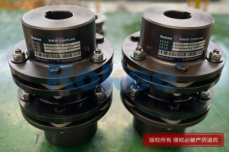
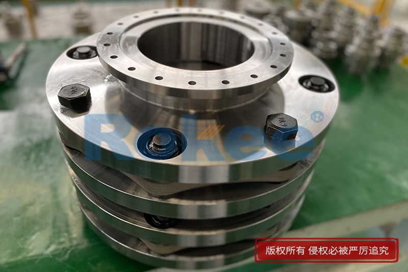

Flexible Diaphragm Coupling is a high-quality product developed independently on basis of combination of advanced products from Europe and Japan, etc. It has smaller size, larger torque of the same model, more reasonable proportioning size, large compensation scope, light weight and small rotational inertia. With modularized design, it’s easy for assembly, maintenance and replacement. Flexible Diaphragm Coupling is widely applied in the fields of fan systems, turboset and other pumps, etc.
![JMI Diaphragm Coupling,Flexible Diaphragm Coupling]()
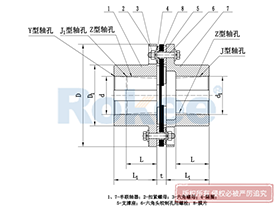
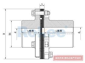
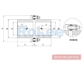
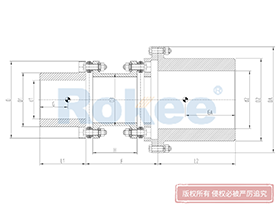
JMI Diaphragm Coupling
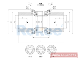
Basic Type, Counterbore
JMI metal diaphragm coupling adopts the single-piece design, suitable for short distance transmission. Besides, the semi-coupling sleeve at one end has a counterbore, facilitating the fixing of the shaft end.View More![JMIJ Diaphragm Coupling,Flexible Diaphragm Coupling]()
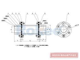
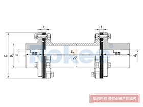
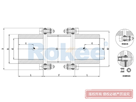
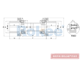
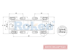
JMIJ Diaphragm Coupling
Counterbore, Intermediate Shaft
JMIJ metal diaphragm coupling is designed with intermediate shaft, suitable for long distance transmission. Besides, the semi-coupling sleeve at one end has a counterbore, facilitating the fixing of the shaft end.View More![JMII Diaphragm Coupling,Flexible Diaphragm Coupling]()
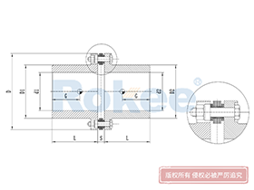
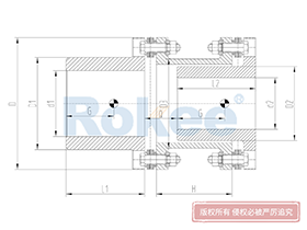
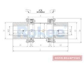
JMII Diaphragm Coupling
Single Section, No Counterbore
JMII metal diaphragm coupling also adopts the single-piece design but has no counterbore, suitable for short distance transmission, with more compact structure.View More![JMIIJ Diaphragm Coupling,Flexible Diaphragm Coupling]()
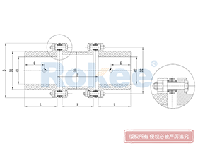
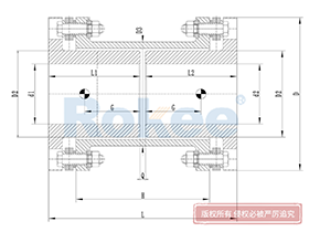
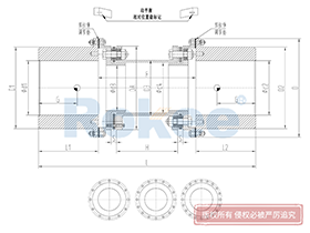
JMIIJ Diaphragm Coupling
No Counterbore, Intermediate Shaft
JMIIJ metal diaphragm coupling is designed with intermediate shaft, suitable for long distance transmission. Besides, the semi-coupling sleeve at both ends have no counterbore.View More![RLM Diaphragm Coupling,Flexible Diaphragm Coupling]()
RLM Diaphragm Coupling
Standard, Single Section, Small-scale
The RLM standard single section small metal diaphragm coupling is suitable for various industrial process pumps and small torque working situations with a working speed not exceeding 5000rpm, and cannot compensate for radial errors.View More![RLMD Diaphragm Coupling,Flexible Diaphragm Coupling]()
RLMD Diaphragm Coupling
Standard, Bimodal, Small-scale
The RLMD standard double section small metal diaphragm coupling is suitable for various industrial process pumps and small torque working occasions with a working speed not exceeding 5000rpm.View More![RLA Diaphragm Coupling,Flexible Diaphragm Coupling]()
RLA Diaphragm Coupling
Standard, Single Section
The classic design of metal flexible diaphragm couplings is a reliable choice for medium to low speed applications, but cannot compensate for radial deviation.View More![RLAD Diaphragm Coupling,Flexible Diaphragm Coupling]()
RLAD Diaphragm Coupling
Standard, Bimodal
The classic design of metal flexible diaphragm couplings is a reliable choice for medium to low speed applications.View More![RLAR Diaphragm Coupling,Flexible Diaphragm Coupling]()
RLAR Diaphragm Coupling
Single Shaft Sleeve, Reverse Installation
Single side shaft sleeve reverse installation design, suitable for occasions with limited shaft head distance.View More![RLARD Diaphragm Coupling,Flexible Diaphragm Coupling]()
RLARD Diaphragm Coupling
Double Shaft Sleeve, Reverse Installation
The double-sided shaft sleeve reverse installation design is also applicable in situations where the distance from the shaft head is limited or the additional bending moment is smaller.View More![RLAF Diaphragm Coupling,Flexible Diaphragm Coupling]()
RLAF Diaphragm Coupling
Large and Small Axis Installation
The size difference design of the bilateral shaft sleeve is suitable for situations where the diameter difference between the two ends of the shaft is significant.View More![RLAT Diaphragm Coupling,Flexible Diaphragm Coupling]()
RLAT Diaphragm Coupling
Extra-long Wheelbase
Adopting an intermediate shaft design, suitable for ultra long shaft spacing power transmission applications.View More![RLQA Diaphragm Coupling,Flexible Diaphragm Coupling]()
RLQA Diaphragm Coupling
No Flange, Quick Installation
Suitable for various industrial process pumps, fans, and other medium to low speed applications, with a maximum speed generally not exceeding 25000 rpm. It meets the requirements of API610/ISO14691 and is one of the first products for API applications.View More![RLQF Diaphragm Coupling,Flexible Diaphragm Coupling]()
RLQF Diaphragm Coupling
Flange Type, Quick Installation
Suitable for drum pressure fans, turbine compressors, and other high speed applications, with a maximum speed of up to 35000rpm.View More![RLQU Diaphragm Coupling,Flexible Diaphragm Coupling]()
RLQU Diaphragm Coupling
Improved Flange, Quick Installation
The improved RLQF has smaller additional bending moments and better performance. Suitable for drum pressure fans, turbine compressors, and other high speed applications.View More![RLHD Diaphragm Coupling,Flexible Diaphragm Coupling]()
RLHD Diaphragm Coupling
High Speed
Suitable for higher speed applications, it also adopts a flexible component integrated assembly design, with a maximum speed of up to 42000rpm.View More
In the realm of mechanical power transmission, couplings serve as critical components that bridge rotating shafts, ensuring efficient torque transfer while accommodating inevitable misalignments. Among the diverse range of couplings available, the flexible diaphragm coupling stands out as a high-performance solution, leveraging metallic elastic elements to achieve reliable transmission in demanding industrial environments. Unlike traditional couplings that rely on rubber or elastomeric components, the flexible diaphragm coupling utilizes thin, precision-engineered metal diaphragms to compensate for shaft deviations, eliminating the need for lubrication and reducing maintenance requirements.
1. Fundamental Definition and Working Principle
A flexible diaphragm coupling is a type of metallic flexible coupling designed to transmit torque between two rotating shafts while accommodating axial, radial, and angular misalignments through the elastic deformation of its diaphragm elements. At its core, the coupling operates on the principle of material flexure: the thin metal diaphragms bend elastically in response to shaft deviations, ensuring continuous contact and torque transfer without introducing excessive stress or wear to the connected shafts or bearings. This mechanism differs significantly from rigid couplings, which offer no misalignment compensation, and elastomeric couplings, which rely on non-metallic materials that may degrade under extreme temperatures or chemical exposure.
The torque transmission process of a flexible diaphragm coupling involves a sequential transfer of rotational force. The driving shaft imparts torque to one half-coupling, which is then transmitted to the diaphragm assembly via bolted connections. The diaphragm, in turn, transfers the torque to the opposite half-coupling, which drives the driven shaft. During this process, any relative displacement between the two shafts (caused by installation errors, thermal expansion, bearing wear, or structural deformation) is absorbed by the elastic deflection of the diaphragm. Importantly, this deflection occurs within the elastic limit of the diaphragm material, ensuring that the coupling retains its original shape and performance characteristics after the misalignment is resolved.
2. Structural Components and Design Variations
The basic structure of a flexible diaphragm coupling consists of three primary components: half-couplings, diaphragm assemblies, and connecting bolts. Each component plays a vital role in ensuring the coupling’s overall performance and reliability.
Half-couplings are typically machined from high-strength metallic materials such as alloy steel or aluminum alloy, depending on the application’s torque and weight requirements. Their primary function is to connect the coupling to the driving and driven shafts, with shaft connection methods including keyway fits, taper fits, or keyless (expansion sleeve) connections. Keyless connections are particularly advantageous in high-speed applications, as they eliminate stress concentrations associated with keyway machining and ensure uniform torque distribution.
Diaphragm assemblies are the core elastic elements of the coupling and are usually fabricated from thin stainless steel sheets, though high-temperature applications may utilize nickel-based alloys such as Inconel. The diaphragms are often designed with corrugated or slotted profiles to enhance their flexibility and stress distribution. Depending on the torque requirements and misalignment compensation needs, diaphragm assemblies may consist of a single diaphragm or multiple stacked diaphragms. Stacked diaphragms increase the coupling’s torque-carrying capacity and improve its ability to absorb larger misalignments. The bolt holes in the diaphragms are typically reinforced with elastic gaskets or chamfered edges to reduce stress concentration, a common failure point in diaphragm couplings.
Connecting bolts are responsible for securing the diaphragm assemblies to the half-couplings. These bolts are usually high-strength fasteners that are tightened to specific torque values to ensure a secure, backlash-free connection. Backlash elimination is critical in precision applications such as servo systems, where even minimal play can lead to positioning errors.
Based on their structural design, flexible diaphragm couplings can be categorized into several common types:
- Single-section diaphragm couplings: Featuring a compact design with a single diaphragm assembly, these couplings are ideal for short-distance shaft connections and applications with moderate misalignment requirements. They are commonly used in small pumps, fans, and machine tool spindles.
- Double-section diaphragm couplings: Equipped with two diaphragm assemblies separated by an intermediate shaft, these couplings offer enhanced misalignment compensation capabilities, particularly for angular and axial displacements. They are suitable for long-distance shaft transmissions and applications where thermal expansion may cause significant axial movement.
- Reverse-mounted diaphragm couplings: Designed with half-couplings that are reverse-mounted to the shaft ends, these couplings are used in applications with limited installation space, such as compact gearboxes and servo motors.
- Long-span diaphragm couplings: Incorporating an extended intermediate shaft, these couplings are specifically designed for ultra-long-distance power transmission, such as in large-scale wind turbines and marine propulsion systems.
3. Key Advantages and Performance Characteristics
Flexible diaphragm couplings offer a range of performance advantages that make them superior to many other coupling types in specific applications. These advantages stem from their metallic construction, elastic diaphragm design, and backlash-free operation.
One of the most significant advantages is the elimination of lubrication requirements. Unlike gear couplings or universal joints, which require regular lubrication to prevent wear and corrosion, flexible diaphragm couplings operate dry. This not only reduces maintenance costs and downtime but also eliminates the risk of lubricant leakage, making them suitable for applications where contamination is a concern, such as food processing, pharmaceutical manufacturing, and chemical processing.
Another key advantage is their excellent misalignment compensation capability. Flexible diaphragm couplings can accommodate axial displacements of up to several millimeters, radial displacements of a few tenths of a millimeter, and angular displacements of up to 1.5 degrees, depending on the design and size of the diaphragm. This capability is crucial in industrial systems where thermal expansion (e.g., in steam turbines) or structural deformation (e.g., in large pumps) can cause significant shaft misalignments.
Flexible diaphragm couplings also exhibit high torque-carrying capacity relative to their size and weight. Their torque transmission range spans from 25 N·m for small-scale applications to over 1,000,000 N·m for heavy-duty industrial systems such as steel rolling mills and gas turbines. This high power-to-mass ratio makes them ideal for high-speed applications, where lightweight components help reduce inertial forces and improve system dynamics.
Other notable advantages include:
- No backlash: The rigid bolted connections between the diaphragms and half-couplings eliminate play, ensuring precise torque transmission and position control in precision systems such as CNC machine tools and servo actuators.
- Wide operating temperature range: Stainless steel diaphragms can operate reliably in temperatures ranging from -20°C to 250°C, while alloy diaphragms can withstand temperatures up to 300°C or higher, making them suitable for high-temperature applications such as exhaust gas recirculation systems and industrial furnaces.
- Corrosion resistance: Stainless steel and nickel-based alloy diaphragms offer excellent resistance to acids, alkalis, and other corrosive media, making them suitable for marine environments, chemical plants, and offshore applications.
- Low noise and vibration: The elastic deformation of the diaphragms helps absorb minor shocks and vibrations, reducing noise levels and extending the service life of connected equipment such as motors and bearings.
- Easy installation and maintenance: Most flexible diaphragm couplings can be installed and removed without moving the connected shafts, and diaphragm replacement (when necessary) can be completed quickly, minimizing downtime.
Despite their numerous advantages, flexible diaphragm couplings do have some limitations. They are generally more expensive than elastomeric couplings, which may be a consideration for low-cost, low-torque applications. Additionally, their radial misalignment compensation capability is typically lower than that of elastomeric couplings, making them less suitable for applications with severe radial misalignments. Finally, the diaphragms are susceptible to fatigue failure if subjected to excessive or repeated misalignments beyond their design limits.
4. Selection Criteria for Flexible Diaphragm Couplings
The proper selection of a flexible diaphragm coupling is critical to ensuring reliable operation, maximizing service life, and minimizing maintenance costs. The selection process involves evaluating several key factors, including torque requirements, shaft misalignment, operating speed, environmental conditions, and shaft dimensions.
4.1 Torque Matching
The first and most important step in coupling selection is to determine the actual torque that the coupling will need to transmit. This includes both the nominal operating torque and the peak torque (e.g., during startup, braking, or load fluctuations). The coupling’s rated torque (Tn) must be greater than the nominal operating torque, typically with a safety factor of 1.2 to 1.5 to account for continuous operation. For applications with frequent start-stop cycles, reverse rotation, or shock loads, a higher safety factor (1.5 to 3.0) is recommended to prevent fatigue failure. The coupling’s maximum torque (Tmax) must also be sufficient to handle short-term peak torques without permanent deformation.
4.2 Speed Compatibility
The coupling’s maximum allowable speed must exceed the actual operating speed of the system, including any transient speed fluctuations. The maximum speed is primarily determined by the diaphragm material’s strength and the coupling’s outer diameter: larger-diameter couplings have lower maximum speeds due to increased centrifugal forces. High-speed applications (e.g., spindle motors, centrifugal compressors) require lightweight couplings with high dynamic balance accuracy (typically G2.5 or higher) to minimize vibration and prevent resonance.
4.3 Misalignment Compensation Requirements
The coupling’s misalignment compensation capabilities must match the expected axial, radial, and angular displacements in the system. These displacements may result from installation errors, thermal expansion, bearing wear, or structural deformation. It is important to select a coupling with compensation values that exceed the actual expected misalignments, as operating beyond the coupling’s compensation limits will significantly reduce the diaphragm’s service life. Double-section diaphragm couplings are generally preferred for applications with large misalignments, as they offer greater flexibility than single-section designs.
4.4 Shaft Dimension Matching
The coupling’s shaft hole diameter must match the diameters of the driving and driven shafts. The fit between the coupling and the shafts is typically a过渡配合 (transition fit) or a small interference fit to ensure a secure connection without excessive stress. The length of the shaft hole must also match the effective length of the shaft ends to prevent insufficient contact and potential slippage. Shaft connection types (keyway, taper, keyless) must be compatible with the shaft design.
4.5 Environmental Adaptability
Environmental factors such as temperature, humidity, corrosive media, and dust must be carefully considered when selecting a coupling. High-temperature applications require diaphragms made of heat-resistant alloys, while corrosive environments demand stainless steel or corrosion-resistant coated components. In dusty or abrasive environments, protective covers may be necessary to prevent debris from accumulating on the diaphragm and causing premature wear.
4.6 Installation and Maintenance Considerations
The coupling’s design should be compatible with the available installation space, ensuring that it does not interfere with other system components. Split-type or modular designs are preferred for applications where access is limited, as they facilitate easier installation and maintenance. Additionally, the availability of replacement parts (such as diaphragms) and the ease of diaphragm replacement should be considered to minimize downtime.
5. Industrial Applications
Due to their unique combination of high performance, reliability, and low maintenance, flexible diaphragm couplings are widely used in a diverse range of industrial sectors and applications. Some of the most common applications include:
5.1 Power Generation
In power generation systems, flexible diaphragm couplings are used to connect gas turbines, steam turbines, and generators. These applications require high torque transmission, high operating speeds, and reliable performance in high-temperature environments. The coupling’s ability to accommodate misalignments caused by thermal expansion and its maintenance-free operation make it ideal for these critical power generation applications. Additionally, the low vibration and backlash-free operation help ensure stable power output.
5.2 Industrial Pumps and Compressors
Pumps and compressors (especially high-power, chemical-resistant pumps) often operate under harsh conditions with significant misalignments and potential exposure to corrosive media. Flexible diaphragm couplings are well-suited for these applications due to their corrosion resistance, lubrication-free operation, and ability to absorb misalignments caused by pump shaft deflection. They are commonly used in centrifugal pumps, reciprocating compressors, and screw compressors in the oil and gas, chemical, and water treatment industries.
5.3 Manufacturing and Machine Tools
In precision manufacturing equipment such as CNC machine tools, servo systems, and robotic arms, flexible diaphragm couplings are used to ensure precise torque transmission and position control. Their backlash-free operation and high torsional stiffness make them ideal for these applications, where even minimal errors can affect product quality. They are also used in printing machinery, textile machinery, and packaging equipment, where high-speed operation and reliable performance are essential.
5.4 Metallurgy and Mining
The metallurgy and mining industries require heavy-duty couplings that can transmit large torques in harsh, dusty, and high-temperature environments. Flexible diaphragm couplings are used in steel rolling mills, blast furnaces, and mining equipment such as conveyors and crushers. Their high torque-carrying capacity, resistance to wear and corrosion, and ability to accommodate misalignments caused by heavy loads make them suitable for these demanding applications.
5.5 Marine and Aerospace
In marine applications, flexible diaphragm couplings are used in ship propulsion systems, connecting diesel engines to propellers. They are also used in offshore oil and gas platforms, where they must withstand corrosive saltwater environments and variable loads. In the aerospace industry, lightweight flexible diaphragm couplings are used to connect aircraft engines to accessory drives, leveraging their high power-to-mass ratio and maintenance-free operation to ensure reliable performance in extreme flight conditions.
5.6 Renewable Energy
In renewable energy systems such as wind turbines, flexible diaphragm couplings are used to connect the turbine rotor to the generator. These applications require couplings that can transmit large torques, accommodate misalignments caused by wind-induced vibrations, and operate reliably in outdoor environments with varying temperatures and humidity. The coupling’s low maintenance requirements are particularly advantageous in wind turbines, which are often located in remote areas.
6. Maintenance and Troubleshooting
While flexible diaphragm couplings are designed for low maintenance, regular inspection and proper care are essential to ensure their long-term reliability and performance. The following maintenance practices are recommended:
6.1 Regular Inspection
Periodic visual inspections should be conducted to check for signs of diaphragm damage, such as cracks, fatigue marks, or deformation. The bolted connections should also be inspected to ensure that they are tight and free from corrosion. In high-speed or critical applications, ultrasonic or magnetic particle testing may be used to detect internal diaphragm defects that are not visible to the naked eye.
6.2 Bolt Torque Checking
The connecting bolts should be checked regularly for proper torque. Loose bolts can cause backlash, uneven torque distribution, and increased stress on the diaphragm, leading to premature failure. Torque checks should be performed after the first 100 hours of operation and at regular intervals thereafter, as specified by the application’s maintenance schedule.
6.3 Diaphragm Replacement
If a diaphragm is found to be damaged or worn, it should be replaced immediately to prevent catastrophic failure of the coupling. Diaphragm replacement is typically a straightforward process that involves removing the connecting bolts, removing the old diaphragm, and installing a new one. It is important to use diaphragms of the same material and design as the original to ensure that the coupling’s performance characteristics are maintained.
6.4 Shaft Alignment Checking
Regular shaft alignment checks are essential to ensure that the misalignment between the driving and driven shafts remains within the coupling’s compensation limits. Misalignment beyond these limits can cause excessive stress on the diaphragm, leading to fatigue failure. Shaft alignment should be checked during installation, after any maintenance work on the connected equipment, and at regular intervals during operation.
6.5 Common Troubleshooting
Some common issues with flexible diaphragm couplings and their solutions include:
- Diaphragm cracking: This is often caused by excessive misalignment, overloading, or loose bolts. The solution involves correcting the shaft alignment, ensuring that the coupling is properly sized for the application, and tightening or replacing the connecting bolts.
- Excessive vibration: Vibration may be caused by unbalanced shafts, misalignment, or worn bearings. The solution involves checking and correcting the shaft alignment, balancing the shafts, and replacing worn bearings.
- Torque transmission failure: This is typically caused by bolt failure or insufficient bolt torque. The solution involves replacing the failed bolts and ensuring that all bolts are tightened to the specified torque.
- Corrosion damage: Corrosion is caused by exposure to corrosive media. The solution involves replacing the corroded components with corrosion-resistant materials and installing protective covers if necessary.
7. Conclusion
Flexible diaphragm couplings represent a sophisticated and reliable solution for power transmission in a wide range of industrial applications. Their unique design, which leverages the elastic deformation of metallic diaphragms, enables them to transmit torque efficiently while accommodating shaft misalignments, eliminating the need for lubrication, and ensuring backlash-free operation. These characteristics make them particularly well-suited for high-speed, high-temperature, corrosive, and precision applications where reliability and low maintenance are critical.
The proper selection of a flexible diaphragm coupling requires careful consideration of torque requirements, operating speed, misalignment compensation needs, shaft dimensions, and environmental conditions. By following the appropriate selection criteria and implementing regular maintenance practices, users can maximize the coupling’s service life, minimize downtime, and ensure the reliable operation of their mechanical systems.
As industrial systems continue to evolve toward higher efficiency, higher speed, and greater precision, the demand for flexible diaphragm couplings is expected to grow. Advances in materials science, such as the development of new high-strength, heat-resistant alloys, and improvements in manufacturing processes, such as precision stamping and laser cutting, will further enhance the performance and versatility of these couplings, making them an even more integral component of modern mechanical power transmission systems.
« Flexible Diaphragm Coupling » Post Date: 2023/7/7
URL: http://www.rokee.com/en/tags/FlexibleDiaphragmCoupling.html