Cardan Shaft Couplings
Rokee is Cardan Shaft Couplings Manufacturer, Customizable according to the cardan shaft couplings drawings provided by the customer, Support Export.
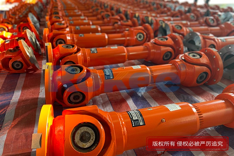
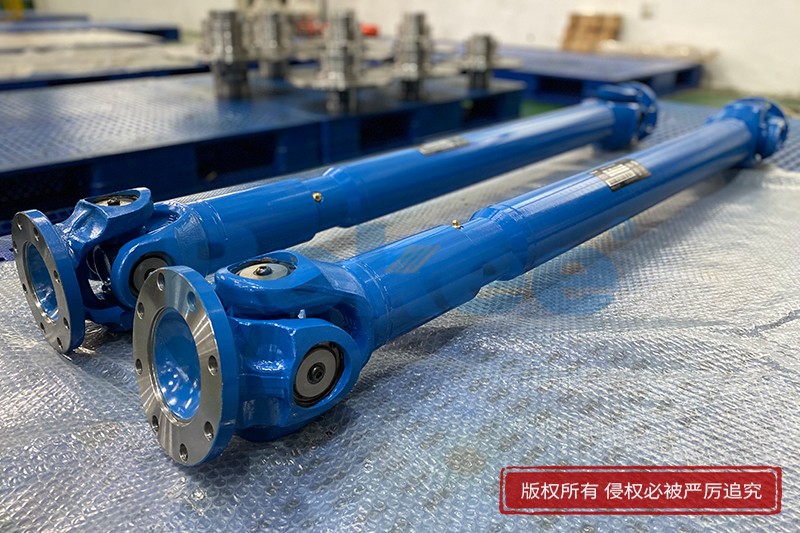
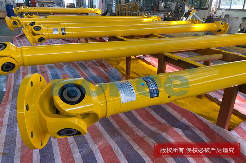
Cardan Shaft Couplings are widely used and have many impressive records. From micro products for modern logistics, artificial intelligence machinery, light products used in the paper industry, high speed and high performance products for engineering and railway vehicles, to super heavy duty products used in metallurgical rolling system systems, Rokee has won us with mature products and quality Long-term trust of customers, widely exported to Europe, America and other parts of the world.
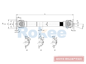
![SWC-BH Universal Coupling,Cardan Shaft Couplings]()
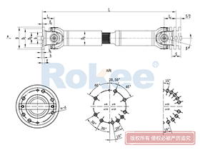
SWC-BH Universal Coupling
standard telescopic welded
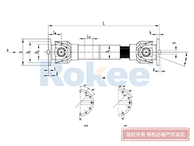
View More![SWC-CH Uuniversal Coupling,Cardan Shaft Couplings]()
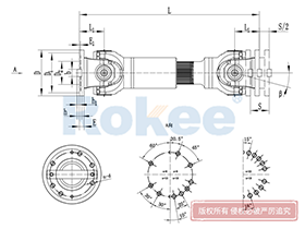
SWC-CH Uuniversal Coupling
Long Telescopic Welded
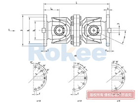
View More![SWC-DH Universal Coupling,Cardan Shaft Couplings]()
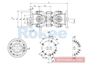
SWC-DH Universal Coupling
Short Telescopic Welded
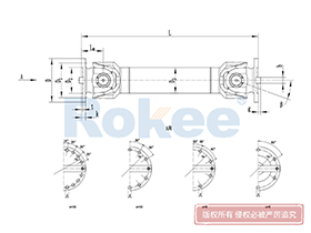
View More![SWC-WD Universal Coupling,Cardan Shaft Couplings]()
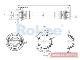
SWC-WD Universal Coupling
Non-telescopic Short
View More![SWC-WH Universal Coupling,Cardan Shaft Couplings]()
SWC-WH Universal Coupling
Non-telescopic Welded
View More![SWP-A Universal Coupling,Cardan Shaft Couplings]()
SWP-A Universal Coupling
Long Type, Telescopic
View More![SWP-B Universal Coupling,Cardan Shaft Couplings]()
SWP-B Universal Coupling
Short Type, Telescopic
View More![SWP-C Universal Coupling,Cardan Shaft Couplings]()
SWP-C Universal Coupling
Short Type, Non-telescopic
View More![SWP-D Universal Coupling,Cardan Shaft Couplings]()
SWP-D Universal Coupling
Long Type, Non-elescopic
View More
In the realm of mechanical power transmission, the ability to transfer torque between misaligned shafts is a critical requirement across countless industrial and automotive applications. Among the various components engineered to meet this demand, the cardan shaft coupling stands out as a robust, versatile, and time-tested solution. Also known as a universal joint coupling, this mechanical device enables the smooth transmission of rotational motion and torque between two shafts that are not perfectly aligned—whether due to angular offset, axial displacement, or radial misalignment. From heavy-duty industrial machinery like rolling mills and cranes to everyday automotive drive shafts, cardan shaft couplings play an indispensable role in ensuring the efficiency and reliability of power transmission systems.
1. Fundamental Concepts: What is a Cardan Shaft Coupling?
A cardan shaft coupling is a mechanical assembly designed to connect two rotating shafts, allowing for the transmission of torque and rotational motion while accommodating various forms of misalignment. Unlike rigid couplings, which require precise alignment between shafts, cardan shaft couplings introduce flexibility into the transmission system, making them ideal for applications where shaft alignment is challenging or dynamic. The core advantage of this coupling type lies in its ability to maintain efficient power transmission even when the connected shafts operate at different angles or experience relative movement during operation.
The term "cardan" originates from the Italian mathematician and physicist Gerolamo Cardano, who first described the mathematical principles underlying the universal joint in the 16th century. While the basic concept has existed for centuries, modern engineering advancements have refined the design and performance of cardan shaft couplings, enabling them to handle higher torque loads, operate at faster speeds, and withstand harsh environmental conditions. Today, they are a staple in industries ranging from automotive and aerospace to mining, manufacturing, and renewable energy.
2. Structural Components and Working Principles
2.1 Core Structural Components
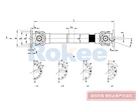
The basic structure of a cardan shaft coupling consists of several key components that work together to facilitate torque transmission and misalignment compensation. While designs may vary based on application requirements, the fundamental components include:
- Yokes (Forks): U-shaped components attached to the ends of the input and output shafts. Each yoke features two arms with bores that house bearings, providing a mounting point for the cross member. The yokes are typically forged or machined to ensure high structural integrity, as they must withstand the torque and forces transmitted through the coupling.
- Cross Member (Spider): A central, cross-shaped component with four trunnions (extensions) that fit into the bearings of the yokes. The cross member is the critical link between the input and output yokes, transferring rotational motion from one yoke to the other. The trunnions are precision-machined to ensure smooth rotation within the bearings.
- Bearings: Located within the yoke bores, these components reduce friction between the cross member trunnions and the yokes. Needle bearings are commonly used in cardan shaft couplings due to their high load-carrying capacity and compact design, which is essential for accommodating the limited space within the yokes.
- Spline Connection (Telescoping Section): Many cardan shaft couplings include a splined section that allows for axial displacement compensation. This section consists of a splined shaft and a splined sleeve, enabling the coupling to adjust to changes in the distance between the input and output shafts during operation. The spline connection also maintains torque transmission while accommodating axial movement.
- Seals and Lubrication Fittings: Seals (such as lip seals or labyrinth seals) prevent contaminants like dust, dirt, and moisture from entering the bearings, which can cause premature wear. Lubrication fittings (grease nipples) allow for the periodic application of lubricant to reduce friction and extend the service life of the bearings and cross member.
2.2 Working Principles
The operation of a cardan shaft coupling is based on the principle of transferring rotational motion through a series of articulated joints. When the input shaft rotates, it drives the attached yoke, which in turn rotates the cross member. The cross member’s trunnions rotate within the bearings of the output yoke, causing the output yoke and connected output shaft to rotate. This mechanism allows for the transmission of torque even when the input and output shafts are misaligned at an angle.
A key characteristic of a single cardan shaft coupling is that it introduces a small degree of velocity fluctuation. As the coupling rotates, the angular velocity of the output shaft varies slightly relative to the input shaft, especially at larger misalignment angles. This fluctuation occurs because the effective radius of the cross member trunnions, as seen from the yoke, changes during rotation. To mitigate this issue, engineers often use double cardan shaft couplings (also known as constant velocity or CV joints), which consist of two single cardan joints arranged in series with a centering yoke between them. The two joints work in tandem to cancel out the velocity fluctuations, ensuring a constant output velocity regardless of the misalignment angle.
The angular compensation capability of a cardan shaft coupling varies depending on the design, but most standard models can accommodate angular misalignment between 5° and 45°. The splined telescoping section allows for axial displacement compensation, with some designs capable of accommodating axial movement up to 5% of the coupling length. This combination of angular and axial compensation makes cardan shaft couplings highly versatile for a wide range of applications.
3. Types of Cardan Shaft Couplings
Cardan shaft couplings are available in various types, each designed to meet specific application requirements such as torque capacity, operating speed, misalignment tolerance, and environmental conditions. The most common types include:
3.1 Single Cardan Shaft Coupling
The single cardan shaft coupling (also known as the cross-type universal joint) is the simplest and most widely used type. It consists of a single cross member connecting two yokes, with bearings in each yoke to facilitate rotation. This type is ideal for applications with moderate torque requirements and small to moderate misalignment angles (typically up to 15°). Common applications include light-duty industrial machinery, agricultural equipment, and some automotive drive shafts (where velocity fluctuation is not a critical concern).
Advantages of single cardan shaft couplings include their simple design, ease of manufacturing, low cost, and easy assembly. Disadvantages include velocity fluctuation at larger misalignment angles, limited torque capacity compared to heavy-duty types, and the need for regular lubrication to prevent wear.
3.2 Double Cardan Shaft Coupling
The double cardan shaft coupling is an improved version of the single type, designed to eliminate velocity fluctuation. It features two single cardan joints connected in series by a centering yoke (also known as an intermediate yoke) and a central shaft. The two joints are aligned such that the velocity fluctuations from the first joint are canceled out by the second joint, resulting in constant velocity transmission. This type can accommodate larger misalignment angles (up to 45° in some designs) and is suitable for high-speed applications where smooth operation is critical.
Double cardan shaft couplings are commonly used in automotive front-wheel drive systems, steering systems, and high-speed industrial machinery such as pumps, compressors, and turbines. Advantages include constant velocity output, high torque capacity, and excellent misalignment compensation. Disadvantages include a more complex design, higher manufacturing cost, and slightly increased size compared to single cardan couplings.
3.3 Ball Cage Cardan Shaft Coupling
The ball cage cardan shaft coupling (a type of CV joint) uses a cage with steel balls instead of a cross member to transmit torque. The inner and outer races of the coupling have grooves that guide the steel balls, ensuring that the balls remain at the midpoint between the input and output shafts at all angles. This design provides constant velocity transmission and can accommodate very large misalignment angles (up to 45° or more).
Ball cage cardan couplings are widely used in automotive applications, particularly in drive shafts for front-wheel drive and all-wheel drive vehicles, as well as in aerospace control systems and high-speed industrial machinery. Advantages include smooth, constant velocity operation, high angular misalignment tolerance, and low noise. Disadvantages include higher cost, sensitivity to contamination (requiring effective sealing), and lower torque capacity compared to heavy-duty cross-type couplings.
3.4 Heavy-Duty Industrial Cardan Shaft Couplings
Heavy-duty cardan shaft couplings are designed for high-torque, low-speed applications in industrial settings such as steel rolling mills, cranes, mining equipment, and large conveyors. These couplings feature robust construction, with large-diameter cross members, heavy-duty bearings, and integrated fork heads for increased structural integrity. Common designs include the SWC and SWP series, which have rotary diameters up to 1600 mm and can transmit torque over distances of more than 30 meters.
Heavy-duty cardan couplings are typically classified based on torque capacity into light, medium, heavy, and super heavy-duty types. They often include features such as reinforced yokes, heat-treated components, and advanced sealing systems to withstand harsh industrial environments. Advantages include high torque capacity, durability, and excellent resistance to shock loads. Disadvantages include large size, high weight, and higher maintenance requirements due to the harsh operating conditions.
3.5 Mini Cardan Shaft Coupling
Mini cardan shaft couplings are compact, lightweight versions designed for small-scale applications with low to moderate torque requirements. They are commonly used in precision machinery, robotics, medical equipment, and small electric motors. These couplings are typically made from lightweight materials such as aluminum or stainless steel and feature small-diameter components to fit in tight spaces.
Advantages of mini cardan couplings include compact size, lightweight design, and ease of integration into small systems. Disadvantages include limited torque capacity and lower misalignment tolerance compared to larger couplings. They are often used in applications where space is a critical constraint and smooth torque transmission is required between small misaligned shafts.
4. Materials and Manufacturing Processes
The performance and service life of a cardan shaft coupling are heavily dependent on the choice of materials and the quality of manufacturing processes. Materials are selected based on factors such as torque capacity, operating environment (temperature, humidity, corrosion), weight requirements, and cost. Manufacturing processes are designed to ensure precision, structural integrity, and consistent performance.
4.1 Common Materials
- Alloy Steels: The most common materials for cardan shaft coupling components (yokes, cross members, shafts) are alloy steels such as 45# steel, 35CrMo, and 20CrMnTi. These steels offer excellent strength, toughness, and wear resistance, making them suitable for high-torque applications. 35CrMo is particularly popular due to its high fatigue strength and ability to withstand shock loads, while 20CrMnTi is often used for components that require carburizing and quenching to achieve a hard surface and tough core.
- Aluminum Alloys: Used in lightweight applications such as mini cardan couplings and automotive components where weight reduction is critical. Aluminum alloys offer good corrosion resistance and are easier to machine than steel, but they have lower torque capacity and strength.
- Stainless Steel: Used in applications where corrosion resistance is essential, such as marine environments, food processing machinery, and chemical plants. Stainless steel couplings are more expensive than steel or aluminum but offer excellent durability in harsh conditions.
- Elastomers: Used in flexible cardan couplings (such as jaw-type cardan couplings) to dampen vibration and absorb shock. Common elastomers include rubber, polyurethane, and neoprene, which offer good flexibility and wear resistance.
4.2 Manufacturing Processes
The manufacturing of cardan shaft couplings involves several sequential processes, each critical to ensuring the final product’s performance and reliability:
1. Raw Material Selection and Preparation: High-quality raw materials (steel bars, aluminum billets, etc.) are selected and inspected for defects. The raw materials are then cut to the required size using sawing or shearing processes.
2. Forging: Most heavy-duty components (yokes, cross members) are forged to improve their structural integrity and mechanical properties. Forging involves heating the raw material to a high temperature and shaping it using pressure from dies. This process aligns the metal’s grain structure, increasing strength and fatigue resistance.
3. Machining: Forged components are precision-machined using lathes, milling machines, and CNC (Computer Numerical Control) machines to achieve the required dimensions and surface finish. Key processes include turning (to shape shafts and trunnions), milling (to create yoke arms and splines), and drilling (to create bearing bores).
4. Heat Treatment: Components are heat-treated to enhance their mechanical properties. Common heat treatment processes include quenching (heating and rapid cooling to harden the metal), tempering (reheating to reduce brittleness), and carburizing (adding carbon to the surface to create a hard, wear-resistant layer). For example, cross members and yokes are often carburized and quenched to achieve a surface hardness of HRC 58-62.
5. Surface Treatment: Components are treated to improve corrosion resistance and appearance. Common surface treatments include painting, galvanizing, and chrome plating. Heavy-duty industrial couplings are often painted with anti-corrosive coatings to withstand harsh environments.
6. Assembly: Machined and treated components are assembled in a specific sequence: bearings are pressed into the yoke bores, the cross member is installed between the yokes, seals are fitted to prevent contamination, and lubrication is applied. The splined section (if included) is assembled to allow for axial movement.
7. Testing and Quality Control: Finished couplings are tested to ensure they meet performance specifications. Common tests include dynamic balancing (to reduce vibration at high speeds), torque testing (to verify load capacity), and visual inspection (to check for defects). Dynamic balancing is particularly important for high-speed applications, with many couplings requiring an imbalance tolerance of ≤0.1g·mm/kg.
Advancements in manufacturing technology, such as CAD (Computer-Aided Design) and CAE (Computer-Aided Engineering), have revolutionized the design and production of cardan shaft couplings. CAD software allows engineers to create 3D models of couplings, enabling detailed stress analysis and dynamic simulation to optimize design and reduce the risk of failure. CAE tools also help in predicting the coupling’s performance under different operating conditions, ensuring that it meets the application’s requirements.
5. Applications of Cardan Shaft Couplings
Cardan shaft couplings are used in a wide range of industries and applications due to their versatility, reliability, and ability to accommodate misalignment. Below are the key application areas:
5.1 Automotive Industry
The automotive industry is one of the largest users of cardan shaft couplings. They are primarily used in drive shafts to transmit power from the engine to the wheels. In rear-wheel drive vehicles, a single or double cardan shaft coupling connects the transmission output shaft to the differential input shaft, accommodating the angular misalignment between the two shafts as the vehicle moves over uneven terrain. In front-wheel drive and all-wheel drive vehicles, ball cage cardan couplings (CV joints) are used in the drive shafts, providing constant velocity transmission and accommodating the large angular misalignment required for steering.
Other automotive applications include steering systems, where cardan couplings allow for the transmission of rotational motion from the steering wheel to the steering rack, and auxiliary systems such as water pumps and alternators.
5.2 Industrial Machinery
Heavy-duty industrial machinery relies heavily on cardan shaft couplings for torque transmission. Key applications include:
- Steel Rolling Mills: Used to connect the motor to the rolling stands, transmitting high torque while accommodating the misalignment caused by the heavy loads and thermal expansion of the equipment. SWC and SWP series heavy-duty couplings are commonly used in this application.
- Cranes and Hoists: Used in the lifting mechanism to transmit torque from the motor to the winch, accommodating the angular misalignment between the motor and the winch shaft as the crane moves.
- Mining Equipment: Used in conveyors, crushers, and drilling machinery, where they must withstand high torque, shock loads, and harsh environmental conditions (dust, moisture, vibration).
- Manufacturing Machinery: Used in pumps, compressors, turbines, and conveyor systems, providing reliable torque transmission and accommodating misalignment between the motor and the driven equipment.
5.3 Aerospace Industry
In the aerospace industry, cardan shaft couplings are used in aircraft control systems, helicopter transmissions, and auxiliary power units (APUs). They must meet strict performance requirements, including lightweight design, high reliability, and resistance to extreme temperatures and pressure. Ball cage cardan couplings are commonly used in aircraft control systems, where precise and smooth motion transmission is critical for flight safety.
5.4 Agricultural Equipment
Agricultural machinery such as tractors, harvesters, and tillers use cardan shaft couplings to transmit power from the engine to various attachments (plows, mowers, balers). These couplings must withstand harsh agricultural environments (dust, dirt, moisture) and accommodate the misalignment caused by the uneven terrain and the movement of the attachments. Single cardan couplings are commonly used in this application due to their simplicity and low cost.
5.5 Renewable Energy Systems
Renewable energy systems such as wind turbines and solar tracking systems use cardan shaft couplings to transmit torque and accommodate misalignment. In wind turbines, couplings are used to connect the rotor to the gearbox and the gearbox to the generator, transmitting high torque while accommodating the misalignment caused by wind loads and thermal expansion. In solar tracking systems, small cardan couplings are used to connect the motor to the tracking mechanism, allowing for precise alignment of the solar panels with the sun.
6. Maintenance and Troubleshooting of Cardan Shaft Couplings
Proper maintenance is essential to ensure the long service life and reliable performance of cardan shaft couplings. Neglecting maintenance can lead to premature wear, component failure, and costly downtime. Below are the key maintenance practices and common troubleshooting techniques:
6.1 Key Maintenance Practices
1. Regular Lubrication: Lubrication is critical to reduce friction between the cross member trunnions and the bearings. The type of lubricant should be selected based on the operating temperature and environment. For example, high-temperature applications may require synthetic lubricants (such as composite calcium sulfonate grease) that can withstand temperatures up to 180°C, while low-temperature applications may require lubricants that remain fluid at -40°C. Lubrication should be performed every 500 hours of operation or every 3 months, with the注脂量 being 1/3 to 1/2 of the bearing cavity volume.
2. Seal Inspection: Seals should be inspected regularly to ensure they are intact and functioning properly. Damaged or worn seals can allow contaminants to enter the bearings, causing premature wear. Seals should be replaced immediately if they show signs of cracking, leaking, or deformation.
3. Bolt Tightening: The bolts that secure the yokes to the shafts should be inspected regularly for tightness. Loose bolts can cause vibration, misalignment, and damage to the coupling and shafts. Bolts should be tightened using a torque wrench to the specified torque value, following a diagonal tightening sequence.
4. Alignment Check: The alignment of the connected shafts should be checked periodically, especially after maintenance or equipment movement. Misalignment beyond the coupling’s tolerance can cause excessive vibration, wear, and reduced service life. Laser alignment tools are recommended for precise alignment, ensuring that the angular misalignment is ≤0.05° and the axial misalignment is ≤0.1mm/m.
5. Dynamic Balancing: High-speed couplings should be dynamically balanced periodically to reduce vibration. Unbalanced couplings can cause excessive stress on the shafts, bearings, and other components, leading to premature failure. Couplings should be balanced to a tolerance of G6.3 or better, as specified by the application requirements.
6. Regular Inspection: A visual inspection of the coupling should be performed regularly to check for signs of wear, damage, or corrosion. Key areas to inspect include the cross member trunnions, bearings, yokes, and splined section. Any signs of excessive wear (such as worn trunnions or loose bearings) should be addressed immediately.
6.2 Common Troubleshooting Issues
Despite proper maintenance, cardan shaft couplings may experience issues due to normal wear, improper installation, or harsh operating conditions. Below are common problems and their solutions:
- Abnormal Vibration and Noise: This is often caused by worn bearings, loose bolts, misalignment, or unbalanced coupling. Solutions include replacing worn bearings, tightening bolts, realigning the shafts, and dynamically balancing the coupling.
- Bearings Wear and Cross Member Failure: Caused by insufficient lubrication, contaminated lubricant, overload, or material fatigue. Solutions include replacing worn bearings and cross members, improving lubrication, installing better seals to prevent contamination, and reducing overload by monitoring torque.
- Lubrication Failure: Caused by worn seals, improper lubricant selection, or infrequent lubrication. Solutions include replacing seals, selecting the correct lubricant, and establishing a regular lubrication schedule.
- Overheating: Caused by excessive friction due to insufficient lubrication, misalignment, or overload. Solutions include lubricating the coupling, realigning the shafts, and reducing the load on the coupling.
- Spline Wear: Caused by insufficient lubrication, contamination, or axial misalignment beyond the coupling’s tolerance. Solutions include lubricating the splined section, installing better seals, and realigning the shafts to reduce axial movement.
6.3 Preventive Maintenance Schedule
Establishing a preventive maintenance schedule is critical to ensuring the reliable performance of cardan shaft couplings. A typical schedule includes:
- Daily/Weekly: Visual inspection for signs of damage, leakage, or abnormal noise; check bolt tightness.
- Monthly: Lubricate the coupling; inspect seals for damage; check alignment.
- Quarterly: Perform detailed inspection of all components; dynamically balance high-speed couplings; replace worn seals or bearings.
- Annually: Complete disassembly and inspection of the coupling; replace worn or damaged components; re-align shafts; update maintenance records.
Maintaining detailed records of all maintenance activities is also important, as it allows engineers to track the coupling’s performance over time and predict when components will need to be replaced.
7. Future Trends in Cardan Shaft Coupling Technology
The cardan shaft coupling industry is continuously evolving, driven by advancements in materials science, manufacturing technology, and the growing demand for more efficient and reliable power transmission systems. Below are the key future trends:
7.1 Material Innovations
The development of new materials is expected to improve the performance and durability of cardan shaft couplings. Advanced composite materials, such as carbon fiber-reinforced polymers (CFRPs), offer high strength-to-weight ratios, making them ideal for lightweight applications such as automotive and aerospace. These materials also offer excellent corrosion resistance and fatigue strength, reducing maintenance requirements and extending service life. Additionally, the use of nanomaterials in lubricants is expected to improve lubrication efficiency, reducing friction and wear.
7.2 Smart Monitoring and Predictive Maintenance
The integration of smart sensors into cardan shaft couplings is a growing trend. Sensors can monitor parameters such as temperature, vibration, torque, and bearing wear in real time, providing data that can be used to predict potential failures before they occur. This enables predictive maintenance, reducing downtime and maintenance costs. For example, embedded wear monitoring chips can detect when the cross member trunnions or bearings are approaching the end of their service life, allowing for timely replacement.
7.3 Design Optimization Using AI and Machine Learning
Artificial intelligence (AI) and machine learning (ML) are being used to optimize the design of cardan shaft couplings. These technologies can analyze large amounts of data from simulations and real-world applications to identify the optimal design parameters for specific applications. This results in couplings that are lighter, more efficient, and more durable, with improved misalignment compensation and torque capacity.
7.4 Increased Efficiency and Reduced Environmental Impact
There is a growing demand for cardan shaft couplings that are more energy-efficient and have a reduced environmental impact. Manufacturers are developing couplings with lower friction losses, improving power transmission efficiency. Additionally, the use of recyclable materials and environmentally friendly lubricants is becoming more common, reducing the environmental footprint of the couplings.
7.5 Customization for Specialized Applications
As industries such as renewable energy, robotics, and aerospace continue to grow, there is an increasing demand for customized cardan shaft couplings designed for specific applications. Manufacturers are using advanced manufacturing processes such as 3D printing to produce custom couplings with complex geometries, allowing for greater flexibility in design and faster production times.
8. Conclusion
Cardan shaft couplings are essential components in power transmission systems, enabling the smooth and reliable transfer of torque between misaligned shafts. Their versatility, robustness, and ability to accommodate various forms of misalignment make them indispensable in a wide range of industries, from automotive and aerospace to industrial manufacturing and renewable energy. Understanding the fundamental principles, types, materials, applications, and maintenance practices of cardan shaft couplings is critical for engineers, maintenance technicians, and industry professionals to ensure the optimal performance and longevity of their equipment.
As technology continues to advance, cardan shaft couplings are expected to become more efficient, durable, and intelligent, with innovations in materials, smart monitoring, and design optimization driving the industry forward. By staying abreast of these trends and implementing proper maintenance practices, organizations can maximize the value of their cardan shaft couplings, reduce downtime, and improve the overall efficiency of their power transmission systems.
« Cardan Shaft Couplings » Post Date: 2023/10/9
URL: http://www.rokee.com/en/tags/cardan-shaft-couplings.html