Tyre Coupling Gap Chart
Rokee® is a well-known high-quality tyre coupling supplier from china, learn more about tyre coupling gap chart, pls contact Rokee technology. Rokee has been established in China since 1999, over the years, with excellent quality, we have been continuously providing many tyre coupling products of various categories and uses complying with multiple standards and a full range of services, from the tyre coupling selection to final installation and operation, for the industry fields of ferrous metallurgy, nuclear power, gas turbine, wind power, ropeway construction, lifting transportation, general equipment, etc.
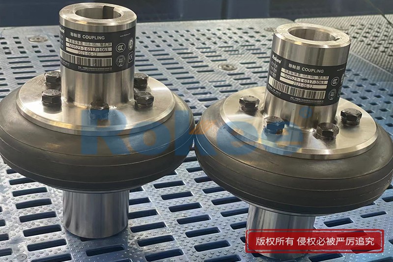
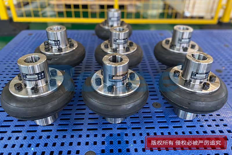
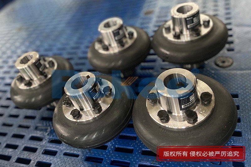
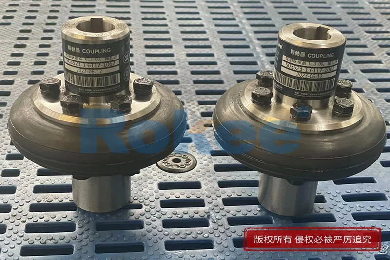
The tyre coupling adopts tyre body-shaped rubber elements, which are connected with two semi-couplings through bolts to realize torque transmission and displacement compensation, tyre coupling has high elastic performance, small torsional rigidity, strong damping capacity, large axial compensation capacity, and good damping performance.
Tyre Coupling Products
-
![UL Elastic Tyre Coupling,Tyre Coupling Gap Chart]()
UL Elastic Tyre Coupling
UL Elastic Tyre Coupling adopts the structure of vulcanizing and bonding the tyre body with the metal connecting plate with threaded holes, which is then directly connected to the two semi-couplings by bolts for torque transmission and other displacement compensation.View More -
![LLA Elastic Tyre Coupling,Tyre Coupling Gap Chart]()
LLA Elastic Tyre Coupling
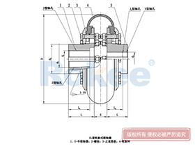
The LLA Elastic Tyre Coupling uses two semi-couplings to connect both sides of the elastic tyre body through internal pressing plates and bolts, making it easy to replace the elastic tyre body.View More -
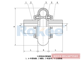
![LLB Elastic Tyre Coupling,Tyre Coupling Gap Chart]()
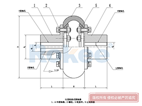
LLB Elastic Tyre Coupling
The LLB Elastic Tyre Coupling is formed by fixing two halves of the coupling and the tire body together through bolts. The shaft hole type can be Y type, J1 type, and Z1 type. It has good shock absorption and excellent inter axle offset compensation performanceView More
In the field of mechanical power transmission, tyre couplings stand out as versatile and reliable components, designed to bridge driving and driven shafts while accommodating misalignment, dampening torsional vibrations, and absorbing sudden load shocks. At the heart of proper tyre coupling deployment lies the tyre coupling gap chart, a foundational technical reference that governs installation accuracy, operational stability, and service longevity. This chart is not merely a collection of numerical values; it is a precise guide that aligns with the physical properties of the coupling’s elastomeric tyre element, the structural design of hub assemblies, and the dynamic demands of connected machinery. Understanding and applying the data within this chart is essential for engineers, maintenance technicians, and installation specialists, as even minor deviations from specified gap parameters can trigger a cascade of performance issues, from accelerated wear and increased noise to premature component failure and unplanned downtime.
To grasp the importance of the tyre coupling gap chart, it is first necessary to define the core gap parameters it outlines and their functional roles within the coupling assembly. The primary gap referenced in the chart is the axial gap between the two hub faces of the tyre coupling, a critical dimension that dictates how the elastomeric tyre element sits, flexes, and transmits torque. This gap is carefully calibrated to balance two key operational needs: sufficient space for the tyre element to move freely and compensate for axial, radial, and angular shaft misalignments, and a tight enough fit to maintain efficient torque transfer without excessive backlash or slippage. Unlike rigid couplings that demand near-perfect shaft alignment, tyre couplings rely on their flexible tyre components to absorb misalignment, but this flexibility is only effective when the axial gap is set according to the chart’s specifications. Additionally, the chart may include secondary gap-related metrics, such as permissible radial clearance limits and angular misalignment thresholds that correlate with the primary axial gap, creating a holistic set of dimensional guidelines for full coupling alignment.
The structure of a standard tyre coupling gap chart is tailored to practical usability, organizing data to match common coupling sizes and operational conditions. Typically, the chart is laid out in a tabular format, with rows corresponding to different tyre coupling model sizes, each engineered to handle specific torque ranges, shaft diameters, and rotational speeds. Columns within the chart detail critical measurements: the recommended nominal axial gap, the acceptable tolerance range for that gap, maximum allowable axial displacement, parallel misalignment limits, and angular misalignment degrees that pair with the specified gap. Each value is derived from rigorous material testing and mechanical engineering calculations, accounting for the elasticity of the tyre element—usually made from durable rubber compounds—the tensile strength of metal hubs, and the thermal expansion characteristics of both the coupling and connected shafts. It is important to note that these values are not arbitrary; they reflect the optimal balance between flexibility and rigidity, ensuring the coupling can perform reliably under both steady-state operation and transient load conditions.
One of the primary functions of the tyre coupling gap chart is to streamline the installation process, eliminating guesswork and ensuring consistency across different applications. Before mounting a tyre coupling, technicians must first position the driving and driven shafts, then set the distance between the two hubs to match the gap specified for the coupling’s size in the chart. This step requires precision measuring tools, such as calipers, feeler gauges, or straight edges, to verify that the gap falls within the stated tolerance range. During installation, the elastomeric tyre element is fitted over the hubs, and clamping rings are secured evenly to hold the tyre in place; the preset gap ensures the tyre is not overcompressed or under-tensioned, which would compromise its performance. Overcompression can cause the tyre to overheat, harden prematurely, or develop cracks under cyclic loading, while insufficient compression leads to slack in the power transmission chain, resulting in torsional backlash, increased vibration, and reduced torque efficiency. The gap chart acts as a safeguard here, providing a clear benchmark to avoid these common installation errors.
Beyond initial installation, the tyre coupling gap chart serves as a vital reference for routine maintenance and condition monitoring, helping teams identify potential issues before they escalate into major failures. Over time, tyre couplings are subjected to continuous operational stress: repeated flexing, exposure to environmental factors like temperature fluctuations, dust, and moisture, and the gradual wear of the elastomeric tyre element. As the tyre degrades, it may lose its original elasticity, causing the axial gap between hubs to shift—either narrowing due to tyre swelling or widening as the material breaks down. By regularly measuring the actual gap between the coupling hubs and comparing it to the chart’s specified values, maintenance personnel can assess the health of the tyre element and the overall coupling assembly. A gap that falls outside the tolerance range indicates that the tyre is worn, damaged, or improperly seated, signaling the need for inspection or replacement. This proactive approach to maintenance, guided by the gap chart, extends the service life of the coupling, reduces the risk of unexpected breakdowns, and optimizes the uptime of the entire power transmission system.
The tyre coupling gap chart also plays a pivotal role in troubleshooting operational anomalies that arise in machinery equipped with tyre couplings. When a system exhibits unusual vibration, excessive noise, inconsistent torque transmission, or overheating near the coupling assembly, the gap between the hubs is one of the first parameters to inspect. A gap that is too small may restrict the tyre’s ability to absorb misalignment, forcing additional stress on shaft bearings and leading to premature bearing failure; a gap that is too large can cause the tyre to whip or flex excessively, generating noise and vibration while reducing power transfer efficiency. By cross-referencing the measured gap with the chart’s data, technicians can quickly isolate whether the issue stems from incorrect gap setting, worn tyre components, or misaligned shafts. This targeted troubleshooting saves time and resources, as it avoids unnecessary disassembly of other system components and allows for precise, effective repairs. In industrial settings where downtime carries significant operational costs, this quick diagnostic capability makes the gap chart an indispensable tool for maintenance teams.
It is crucial to recognize that the tyre coupling gap chart is not a one-size-fits-all document, and its values must be applied with consideration for the specific operating environment and application requirements. While the chart provides standard gap specifications for general-purpose use, adjustments may be necessary for specialized conditions. For example, in applications with extreme temperature variations—whether high heat that causes thermal expansion or cold temperatures that stiffen the elastomeric tyre—the nominal gap may need to be fine-tuned within the chart’s tolerance range to accommodate material changes. Similarly, heavy-duty applications with frequent load shocks or high rotational speeds may require adhering to the tighter end of the gap tolerance to enhance stability, while light-duty, low-speed systems may operate effectively within the wider tolerance range. Technicians must combine the chart’s data with their knowledge of the machinery’s duty cycle, environmental conditions, and performance demands to make informed decisions, ensuring the coupling operates at peak efficiency without compromising durability.
Another key aspect of working with the tyre coupling gap chart is understanding the relationship between gap settings and overall system alignment. Even if the axial gap is set perfectly per the chart, poor radial or angular shaft alignment can negate these efforts and place undue stress on the coupling. The gap chart often complements alignment guidelines, with specified gap values paired with maximum allowable misalignment limits to ensure full compliance with design parameters. Proper shaft alignment, combined with accurate gap setting, maximizes the coupling’s ability to absorb residual misalignment and vibrations, protecting both the coupling and connected equipment from damage. This synergy between gap control and alignment highlights the chart’s role as part of a broader mechanical best practices framework, emphasizing that precision in one area supports reliability across the entire power transmission system.
In industrial sectors ranging from manufacturing and material handling to mining, agriculture, and marine engineering, tyre couplings are ubiquitous, powering conveyor systems, pumps, fans, compressors, and a host of other rotating machinery. In each of these sectors, the tyre coupling gap chart remains a constant, unifying technical reference that ensures consistency in installation and maintenance across diverse work sites and teams. Standardized gap specifications reduce the risk of human error, simplify training for new technicians, and ensure that couplings perform consistently regardless of where they are installed. For facilities managing large fleets of machinery with multiple tyre couplings, the chart also aids in inventory management and replacement planning, as technicians can quickly reference the required gap for each coupling size to source compatible replacement parts and plan maintenance schedules efficiently.
As mechanical engineering and power transmission technology continue to evolve, the tyre coupling gap chart remains a timeless and essential tool, adapting to new coupling designs and material advancements while retaining its core purpose: to provide clear, accurate dimensional guidance for optimal coupling performance. Modern iterations of the chart may integrate digital formats for easier access on job sites, or include additional metrics related to advanced elastomeric materials, but the fundamental focus on precise gap specification remains unchanged. This continuity speaks to the chart’s value; it is a practical, evidence-based resource that bridges theoretical engineering design and real-world mechanical application, turning complex technical requirements into actionable steps for installation and maintenance teams.
In summary, the tyre coupling gap chart is far more than a supplementary technical document—it is the backbone of proper tyre coupling utilization, influencing every stage from initial installation to long-term operational maintenance and troubleshooting. By defining precise gap parameters and tolerance ranges, it ensures that tyre couplings deliver on their promise of flexible, reliable power transmission, protecting machinery, reducing wear, and enhancing operational efficiency. Neglecting the guidelines outlined in the chart can lead to subpar performance, increased maintenance costs, and premature component failure, while strict adherence to its specifications unlocks the full potential of tyre couplings in diverse industrial applications. For professionals working with mechanical power transmission systems, mastering the tyre coupling gap chart is not just a best practice—it is an essential skill that underpins safe, efficient, and sustainable machinery operation. As industrial operations continue to prioritize reliability and uptime, the role of the tyre coupling gap chart will only grow more critical, serving as a steadfast guide for maintaining the integrity of rotating equipment across countless industrial applications.
« Tyre Coupling Gap Chart » Update Date: 2026/3/7
URL: http://www.rokee.com/en/blog/tyre-coupling-gap-chart.html
Tags: Rubber Tyre Couplings , Tyre Couplings , Flexible Tyre Couplings , sandwich panel machine