Jaw Coupling Size Chart
Rokee® is a well-known high-quality jaw coupling supplier from china, learn more about jaw coupling size chart, pls contact Rokee technology. Rokee has been established in China since 1999, over the years, with excellent quality, we have been continuously providing many jaw coupling products of various categories and uses complying with multiple standards and a full range of services, from the jaw coupling selection to final installation and operation, for the industry fields of ferrous metallurgy, nuclear power, gas turbine, wind power, ropeway construction, lifting transportation, general equipment, etc.
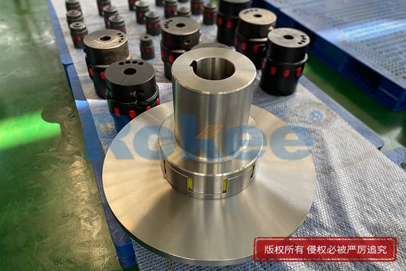

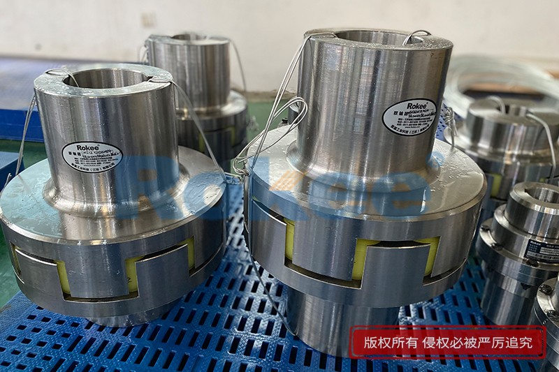
The jaw coupling is composed of two semi-couplings with convex claws and a plum-shaped flexible non-metallic element whose hardness can be adjusted. By embedding the plum-shaped flexible element into the two semi-couplings to realize the connection, it has the characteristics of compensating the relative displacement of the two axes, reducing vibration and buffering, simple structure and easy maintenance without lubrication.
The jaw coupling is a material flexing coupling that transmits torque thru compression of an elastomeric spider insert placed between two intermeshing jaws.
Jaw Coupling Products
-
![LM/ML Plum-shaped Flexible Coupling,Jaw Coupling Size Chart]()
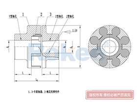
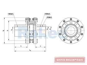
LM/ML Plum-shaped Flexible Coupling
Basic Type
LM Plum-shaped Flexible Coupling is the basic form of this series of couplings.View More -
![LMD/MLZ Plum-shaped Flexible Coupling,Jaw Coupling Size Chart]()
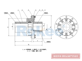
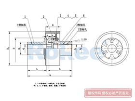
LMD/MLZ Plum-shaped Flexible Coupling
Single Flange
LMD Plum-shaped Flexible Coupling is added with transition connection, which eliminates the need of axially moving the semi-coupling when replacing the elastomer.View More -
![LMS/MLS Plum-shaped Flexible Coupling,Jaw Coupling Size Chart]()
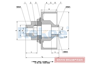
LMS/MLS Plum-shaped Flexible Coupling
Double Flange
LMS Plum-shaped Flexible Coupling adopts double transition flange connection, which eliminates the need of axially moving the semi-coupling when replacing the elastomer.View More -
![LMZ-I/MLL-I Plum-shaped Flexible Coupling,Jaw Coupling Size Chart]()
LMZ-I/MLL-I Plum-shaped Flexible Coupling
Split Type, With Brake Wheel
LMZ-I Plum-shaped Flexible Coupling adopts split brake wheel design, suitable for situations where braking is required.View More -
![LMZ-II/MLL-II Plum-shaped Flexible Coupling,Jaw Coupling Size Chart]()
LMZ-II/MLL-II Plum-shaped Flexible Coupling
Integral, With Brake Wheel
LMZ- II Plum-shaped Flexible Coupling adopts integral brake wheel design, suitable for situations where braking is required.View More -
![LMPK/MLPK Plum-shaped Flexible Coupling,Jaw Coupling Size Chart]()
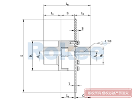
LMPK/MLPK Plum-shaped Flexible Coupling
Split Type, With Brake Discs
LMPK Plum-shaped Flexible Coupling adopts split brake disc design, suitable for situations where braking is required and eliminating the need of axially moving the semi-coupling when replacing the elastomer.View More

In the intricate landscape of industrial power transmission, jaw couplings stand as one of the most widely utilized and reliable components, bridging the gap between driving and driven shafts while accommodating misalignment, dampening vibration, and transmitting torque efficiently. At the heart of selecting, installing, and maintaining these critical components lies the jaw coupling size chart—a foundational reference tool that consolidates critical dimensional, performance, and compatibility data into a structured, easy-to-navigate format. Far more than a simple list of measurements, this chart serves as a roadmap for engineers, maintenance technicians, and procurement professionals, ensuring that every jaw coupling chosen aligns perfectly with the unique demands of its application, whether in light-duty machinery, heavy industrial equipment, or precision-driven systems.
To fully grasp the significance of the jaw coupling size chart, it is first essential to revisit the core design of a standard jaw coupling. Composed of two rigid metal hubs and a flexible elastomeric spider insert, this three-piece construction balances robustness and versatility. The hubs, typically crafted from durable metals like aluminum alloy, steel, or stainless steel, feature precision-machined jaws that interlock with the spider’s lobes, creating a secure connection for torque transfer. The elastomeric spider, available in various material formulations to suit different operating conditions, acts as a shock absorber, reducing vibration transmission between shafts and compensating for minor shaft misalignments that are inevitable in real-world industrial setups. Each component’s dimensions—from hub outer diameter and bore size to spider lobe dimensions and overall coupling length—are standardized across size ranges, and these precise measurements are meticulously organized within the size chart to eliminate guesswork and ensure seamless compatibility between mating parts.
A well-constructed jaw coupling size chart encompasses a comprehensive array of parameters, each serving a distinct purpose in the selection and application process. One of the most fundamental metrics featured is the nominal size designation, a simplified alphanumeric code that categorizes couplings by their overall dimensional and performance capabilities. These size designations follow a consistent scaling pattern, with smaller codes corresponding to compact, low-torque couplings and larger codes indicating heavy-duty, high-torque units designed for demanding industrial tasks. Beyond the nominal size, the chart details critical outer dimensions, including hub outer diameter, overall coupling length, and hub length—measurements that dictate whether the coupling will fit within the spatial constraints of the equipment, a vital consideration in compact machinery or densely configured power transmission systems where clearance is limited.
Bore size specifications represent another cornerstone of the jaw coupling size chart, as these dimensions directly determine the coupling’s compatibility with the shafts it connects. The chart typically lists both minimum and maximum allowable bore diameters for each size, covering both imperial and metric measurements to accommodate global industrial standards. Accompanying bore sizes are detailed keyway dimensions, including keyway width, depth, and length, which ensure a secure, slip-resistant connection between the hub and shaft via a standard key. Some charts also include specifications for alternative shaft fastening methods, such as set screw locations or clamp-style hubs, providing additional flexibility for different shaft mounting requirements. Precision in bore and keyway measurements is non-negotiable; even a minor deviation can lead to unstable operation, premature wear, or catastrophic failure under load, making the chart’s accurate data indispensable for proper fitment.
Torque transmission capabilities are arguably the most performance-critical data points in the jaw coupling size chart, as they define the coupling’s ability to handle the operational loads of the application. The chart outlines rated torque values, which represent the maximum continuous torque a coupling can transmit reliably without compromising performance or durability. These values are often presented across different elastomer materials, as the hardness and composition of the spider insert directly impact torque capacity—softer elastomers offer enhanced vibration damping but lower torque ratings, while stiffer formulations deliver higher torque transmission with slightly reduced damping properties. Additionally, the chart may include peak or overload torque values, which account for sudden shocks, start-stop cycles, or transient loads common in machinery such as pumps, conveyors, and mixers. By cross-referencing these torque figures with the application’s calculated torque requirements, users can select a coupling size that avoids under-sizing (which leads to failure) and over-sizing (which adds unnecessary weight and cost).
Speed ratings are another vital parameter integrated into the jaw coupling size chart, closely tied to the coupling’s dimensional stability and dynamic balance. Maximum rotational speed limits are specified for each size, reflecting the coupling’s ability to operate smoothly at high RPM without experiencing excessive vibration, heat buildup, or mechanical stress. Smaller jaw couplings, with their compact size and lower mass, typically feature higher speed ratings, making them suitable for precision equipment like small motors, fans, and instrumentation. Larger, heavier couplings, built for high torque, have lower maximum speed thresholds to maintain operational integrity. Operating a coupling beyond its rated speed can cause the elastomeric spider to degrade rapidly, warp the metal hubs, or create dangerous imbalances that damage surrounding equipment, making the chart’s speed guidelines a critical safety and performance benchmark.
Misalignment compensation data, though often overlooked by novice users, adds immense practical value to the jaw coupling size chart. Every jaw coupling is engineered to tolerate three types of shaft misalignment: angular, parallel, and axial. The chart quantifies the allowable limits for each type, specifying the maximum angular offset (in degrees), parallel offset (in millimeters or inches), and axial movement (in millimeters or inches) that a given size can accommodate without excessive wear or performance loss. This data is essential for applications where perfect shaft alignment is unachievable, such as mobile machinery, systems with thermal expansion, or equipment assembled in field conditions. By aligning the coupling’s misalignment capabilities with the actual shaft offset in the application, users can prevent premature failure of the spider insert and reduce wear on bearings, seals, and other adjacent components, lowering long-term maintenance costs.
Operating temperature ranges are also prominently featured in the jaw coupling size chart, as environmental conditions directly impact the performance and longevity of the elastomeric spider. Different elastomer materials have distinct temperature resistance profiles, and the chart maps these profiles to each coupling size, indicating the minimum and maximum temperatures in which the coupling can operate reliably. Standard elastomers perform well in moderate temperature ranges, while specialized formulations extend compatibility to extreme cold or high-heat environments, such as industrial furnaces, cold storage facilities, or outdoor machinery in harsh climates. Selecting a coupling size paired with a temperature-appropriate spider, guided by the chart, ensures that the elastomer retains its flexibility and structural integrity, avoiding brittleness in cold conditions or melting and deformation in heat.
Beyond individual parameters, the jaw coupling size chart is designed to streamline the end-to-end selection process, guiding users through a logical sequence of checks to find the optimal coupling. The process typically begins with measuring the diameter of the driving and driven shafts to narrow down bore size compatibility, then moves to calculating the application’s torque and speed requirements to match with the chart’s performance ratings. Next, users assess spatial constraints to confirm overall dimensional fit, followed by evaluating misalignment and temperature conditions to select the right spider material. This sequential workflow, supported by the chart’s organized data, eliminates common selection errors and ensures that every chosen coupling is tailored to the application’s unique needs. Whether replacing a worn coupling in an existing system or specifying components for new equipment, the chart transforms complex technical decisions into a straightforward, repeatable process.
In practical industrial operations, the jaw coupling size chart plays a pivotal role in maintenance and replacement workflows as well. When a coupling fails or wears out, technicians can quickly reference the chart to identify the exact replacement size using the existing coupling’s nominal designation or dimensional measurements, reducing equipment downtime. For preventive maintenance, the chart helps teams anticipate wear patterns—for example, identifying that a smaller coupling size in a high-vibration application may require more frequent spider replacements—and schedule maintenance proactively. Additionally, the chart aids in inventory management, allowing facilities to stock the most commonly used coupling sizes and spare spiders based on their equipment fleet’s needs, minimizing stockouts and excess inventory.
It is important to note that while jaw coupling size charts follow broad industry standards for consistency, slight variations in dimensional tolerances and performance ratings may exist between different manufacturing frameworks. These variations are minor and do not impact core compatibility, as the chart’s primary function is to provide standardized, actionable data rather than proprietary specifications. Users should focus on the consistency of measurements and performance metrics within a single chart, ensuring that all selected components—hubs and spiders—align with the same size designation to maintain assembly integrity. Cross-referencing multiple charts can also provide valuable context, confirming that torque, speed, and dimensional data align across industry norms for added confidence in selection.
The versatility of jaw couplings, reflected in the breadth of the size chart, makes them suitable for an expansive range of industrial applications, and the chart’s data directly correlates to these use cases. Smaller jaw coupling sizes, with compact dimensions, low torque ratings, and high speed capabilities, are ideal for light-duty applications such as small electric motors, laboratory equipment, ventilation fans, and precision conveyors. Mid-range sizes strike a balance between torque and speed, fitting seamlessly into pumps, compressors, gearboxes, and material handling systems that demand moderate power transmission and vibration damping. Larger, heavy-duty sizes, featured in the upper ranges of the chart, are engineered for high-torque, low-speed applications including industrial mixers, crushers, large conveyor systems, and heavy machinery in mining, manufacturing, and construction. In every case, the size chart serves as the critical link between the coupling’s capabilities and the application’s demands.
Investing time in understanding the jaw coupling size chart yields tangible benefits across operational, financial, and safety metrics. Operationally, it ensures smooth power transmission, reduced vibration, and consistent equipment performance, enhancing overall productivity. Financially, it prevents costly mistakes from incorrect coupling selection, minimizes maintenance and replacement expenses, and extends the lifespan of connected machinery. From a safety perspective, it reduces the risk of coupling failure, which can lead to equipment damage, production halts, or workplace accidents. In an era where industrial efficiency and reliability are paramount, the jaw coupling size chart is not just a reference tool—it is a foundational element of responsible equipment design, maintenance, and operation.
In summary, the jaw coupling size chart is an indispensable resource in the field of industrial power transmission, distilling complex dimensional, performance, and compatibility data into a accessible, practical format. It empowers users to make informed decisions, from initial component selection to ongoing maintenance, ensuring that jaw couplings perform optimally in every application. By mastering the details of the size chart—from bore sizes and torque ratings to misalignment limits and temperature ranges—professionals can unlock the full potential of jaw couplings, creating robust, efficient, and long-lasting power transmission systems. As industrial technology continues to evolve, the jaw coupling size chart remains a constant, reliable guide, adapting to new applications and maintaining its role as a cornerstone of effective mechanical engineering and equipment management.
« Jaw Coupling Size Chart » Update Date: 2026/3/7
URL: http://www.rokee.com/en/blog/jaw-coupling-size-chart.html
Tags: Multi Jaw Couplings , Stainless Steel Jaw Couplings , Curved Jaw Couplings , Jaw Coupling Spiders , Jaw Couplings , sandwich panel machine