Cross Cardan Shafts 3D Model
Rokee® is a well-known high-quality cross cardan shaft supplier from china, learn more about cross cardan shafts 3d model, pls contact Rokee technology. Rokee has been established in China since 1999, over the years, with excellent quality, we have been continuously providing many cross cardan shaft products of various categories and uses complying with multiple standards and a full range of services, from the cross cardan shaft selection to final installation and operation, for the industry fields of ferrous metallurgy, nuclear power, gas turbine, wind power, ropeway construction, lifting transportation, general equipment, etc.
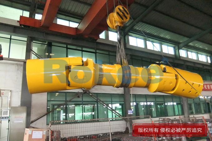
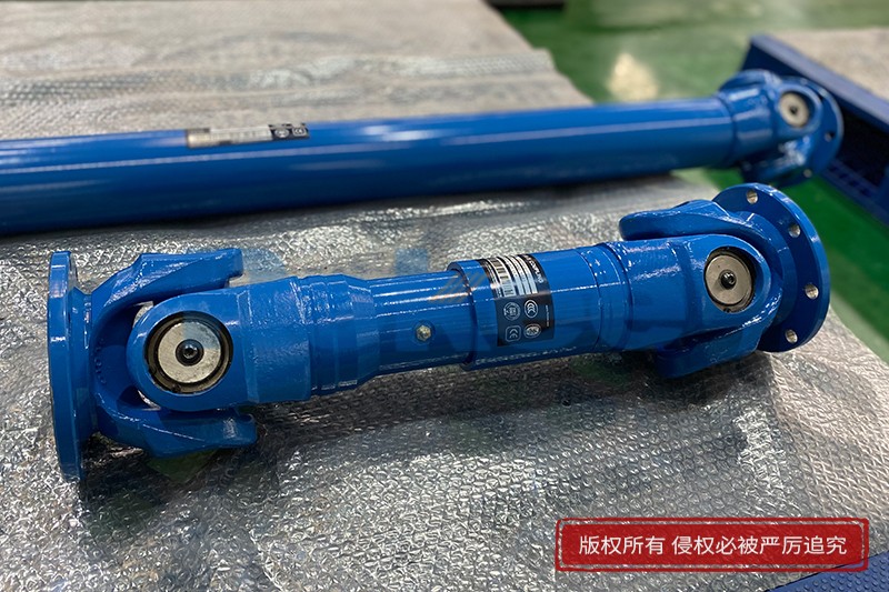
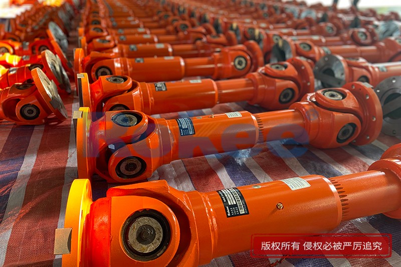
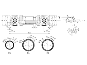
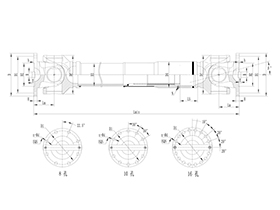
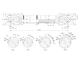
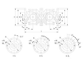
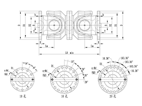
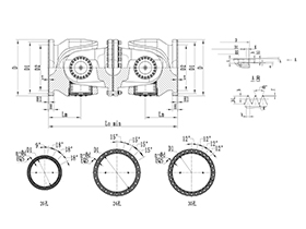
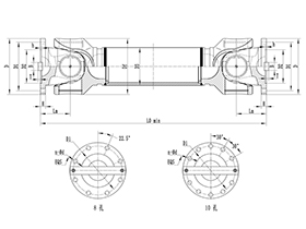
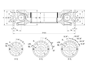
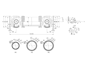
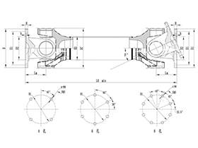
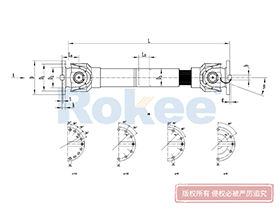
The cross cardan shaft uses cross bearings to connect the flanges at both ends, which can transmit torque that is not on the same axis. The diagonal compensation can reach more than 25°, and the spline connection can compensate for the axial displacement in a large distance. With high carrying capacity and excellent transmission efficiency, cross cardan shaft is widely used in modern industrial fields.
Cross Cardan Shaft Products
-
![ROWS-BH Cardan Shaft,Cross Cardan Shafts 3D Model]()
ROWS-BH Cardan Shaft
View More -
![ROWL-BH Cardan Shaft,Cross Cardan Shafts 3D Model]()
ROWL-BH Cardan Shaft
View More -
![ROWM-BH Cardan Shaft,Cross Cardan Shafts 3D Model]()
ROWM-BH Cardan Shaft
View More -
![ROWH-BH Cardan Shaft,Cross Cardan Shafts 3D Model]()
ROWH-BH Cardan Shaft
View More -
![ROWS-WD Cardan Shaft,Cross Cardan Shafts 3D Model]()
ROWS-WD Cardan Shaft
View More -
![ROWM-WD Cardan Shaft,Cross Cardan Shafts 3D Model]()
ROWM-WD Cardan Shaft
View More -
![ROWH-WD Cardan Shaft,Cross Cardan Shafts 3D Model]()
ROWH-WD Cardan Shaft
View More -
![ROWL-WD Cardan Shaft,Cross Cardan Shafts 3D Model]()
ROWL-WD Cardan Shaft
View More -
![ROWM-WH Cardan Shaft,Cross Cardan Shafts 3D Model]()
ROWM-WH Cardan Shaft
View More -
![ROWH-WH Cardan Shaft,Cross Cardan Shafts 3D Model]()
ROWH-WH Cardan Shaft
View More -
![ROWL-WH Cardan Shaft,Cross Cardan Shafts 3D Model]()
ROWL-WH Cardan Shaft
View More -
![ROWS-WH Cardan Shaft,Cross Cardan Shafts 3D Model]()
ROWS-WH Cardan Shaft
View More -
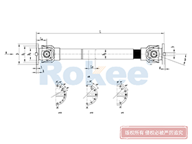
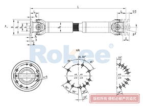
![SWC-BH Universal Coupling,Cross Cardan Shafts 3D Model]()
SWC-BH Universal Coupling
standard telescopic welded
View More -
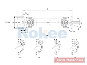
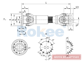
![SWC-CH Uuniversal Coupling,Cross Cardan Shafts 3D Model]()
SWC-CH Uuniversal Coupling
Long Telescopic Welded
View More -
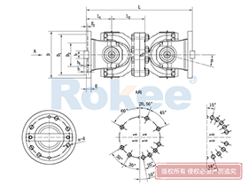
![SWC-DH Universal Coupling,Cross Cardan Shafts 3D Model]()
SWC-DH Universal Coupling
Short Telescopic Welded
View More -
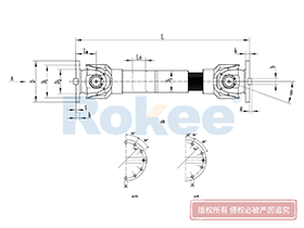
![SWC-WD Universal Coupling,Cross Cardan Shafts 3D Model]()
SWC-WD Universal Coupling
Non-telescopic Short
View More -
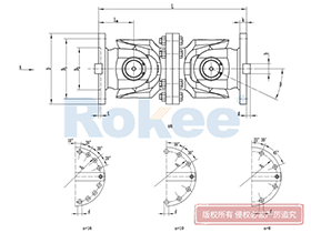
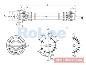
![SWC-WH Universal Coupling,Cross Cardan Shafts 3D Model]()
SWC-WH Universal Coupling
Non-telescopic Welded
View More -
![SWP-A Universal Coupling,Cross Cardan Shafts 3D Model]()
SWP-A Universal Coupling
Long Type, Telescopic
View More -
![SWP-B Universal Coupling,Cross Cardan Shafts 3D Model]()
SWP-B Universal Coupling
Short Type, Telescopic
View More -
![SWP-C Universal Coupling,Cross Cardan Shafts 3D Model]()
SWP-C Universal Coupling
Short Type, Non-telescopic
View More -
![SWP-D Universal Coupling,Cross Cardan Shafts 3D Model]()
SWP-D Universal Coupling
Long Type, Non-elescopic
View More
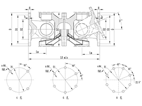

In the intricate landscape of mechanical engineering and power transmission systems, cross cardan shafts stand as one of the most fundamental and widely utilized components, bridging the gap between misaligned rotating shafts and enabling seamless torque transfer across diverse industrial setups. The development and application of 3D models for these critical components have revolutionized the way engineers design, analyze, test, and optimize cross cardan shafts, eliminating the limitations of traditional 2D drafting and bringing a new level of precision, efficiency, and practicality to every stage of the product lifecycle. A cross cardan shaft, at its core, is a mechanical coupling built around a central cross-shaped spindle, paired with two yoke assemblies that connect to driving and driven shafts respectively, with bearing sets facilitating smooth articulation between the cross and yokes. This seemingly straightforward structure belies its complex kinematic behavior and load-bearing requirements, making 3D modeling an indispensable tool for unlocking its full potential and ensuring reliable performance in real-world operating conditions.
To fully grasp the value of cross cardan shafts 3D models, it is essential to first understand the foundational design and functional logic of the physical component. Unlike rigid shaft couplings that demand perfect axial alignment between connected shafts, cross cardan shafts thrive in scenarios where shafts intersect at an angle, run parallel but offset, or experience dynamic positional shifts during operation. The cross-shaped spindle, with its four perpendicular journals, acts as the pivotal hinge, allowing the two yokes to rotate independently within a defined angular range—typically between 5 and 45 degrees, depending on design specifications and application needs. This flexibility addresses common engineering challenges such as installation inaccuracies, thermal expansion-induced displacement, and mechanical vibration, which are unavoidable in heavy machinery, automotive systems, agricultural equipment, and industrial manufacturing lines. Each element of the cross cardan shaft, from the profile of the yoke arms and the diameter of the cross journals to the type and placement of bearings, plays a vital role in determining torque capacity, rotational speed limits, wear resistance, and overall service life, and these nuances are captured with meticulous detail in a high-fidelity 3D model.
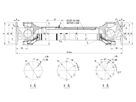
The process of creating a precise cross cardan shafts 3D model begins with a deep dive into dimensional specifications and geometric constraints, laying the groundwork for a digital replica that mirrors the physical part in every measurable aspect. Engineers start by defining core parameters: the outer diameter of the cross spindle, the length and thickness of the yoke arms, the bore size for shaft connection, the dimensions of bearing seats, and the clearance tolerances between mating components. Using advanced computer-aided design (CAD) software, they construct each individual part as a separate 3D entity, focusing on geometric accuracy and adherence to engineering standards. This stage is not merely about replicating shapes; it involves integrating functional design elements, such as fillets and radii to reduce stress concentrations at critical load points, tapered surfaces for optimal bearing fit, and reinforced sections to enhance structural rigidity under heavy torque loads. Unlike 2D drawings that rely on multiple views and annotations to convey depth and dimension, a 3D model presents a fully immersive, volumetric representation, allowing designers to rotate, zoom, and inspect the component from any angle, instantly identifying geometric flaws or interferences that might go unnoticed in flat sketches.
Once the individual part models are finalized, the next step is assembly modeling, where the separate components of the cross cardan shaft are brought together in a digital environment to replicate the real-world mechanical configuration. This assembly process is critical for validating the functional integrity of the design, as it simulates the physical interaction between the cross spindle, yokes, bearings, and retaining clips. Engineers can test the range of motion of the assembled joint, ensuring that the yokes can pivot freely through the intended angular spectrum without binding or contact between adjacent parts. They can also verify the fit of bearings within the cross journals and yoke seats, confirming that there is adequate space for lubrication flow and that preload settings align with performance requirements. This digital assembly eliminates the need for costly physical prototypes in the early design stages, enabling teams to iterate quickly and refine the design based on real-time feedback. For instance, if the 3D assembly reveals that the yoke arms interfere with the cross spindle at maximum angular deflection, designers can adjust the arm length or contour immediately, streamlining the development workflow and reducing the risk of costly rework later in production.
Beyond basic design and assembly, cross cardan shafts 3D models serve as a powerful platform for engineering simulation and performance analysis, elevating the design process from intuitive drafting to data-driven optimization. By integrating the 3D model with finite element analysis (FEA) tools, engineers can simulate a wide range of operating conditions to assess the component’s structural strength, stress distribution, and durability. They can apply variable torque loads, rotational speeds, and angular misalignments to the model, mapping areas of high stress, strain, or deformation that could lead to premature failure under real-world use. This analysis helps optimize material selection, wall thickness, and geometric features to enhance load-bearing capacity without unnecessary excess weight, striking a balance between performance and efficiency. Additionally, kinematic simulation tools can be used to study the motion characteristics of the cross cardan shaft, including velocity fluctuations and torque ripple that occur as the joint rotates at an angle. For applications requiring uniform rotational output, such as precision machinery, these simulations guide the design of dual joint configurations that cancel out undesirable motion variations, ensuring smooth power transmission even at significant shaft angles.
The utility of cross cardan shafts 3D models extends far beyond the design and engineering phases, permeating manufacturing, quality control, and aftermarket support with tangible benefits. In manufacturing, the 3D model serves as a master digital blueprint, guiding computer numerical control (CNC) machining, casting, forging, and additive manufacturing processes with unparalleled accuracy. Machinists can extract precise tool paths, dimensional tolerances, and geometric specifications directly from the model, minimizing human error and ensuring consistency across production runs. This digital continuity reduces scrap rates, shortens production lead times, and simplifies the manufacturing of complex, custom-sized cross cardan shafts tailored to unique industrial applications. For quality control teams, the 3D model provides a reference standard for inspecting finished parts, using coordinate measuring machines (CMMs) and 3D scanning tools to compare physical components against the digital model and verify compliance with design requirements. Even in maintenance and repair, 3D models prove invaluable: technicians can access detailed digital representations of the shaft assembly to understand disassembly sequences, identify worn components, and source replacement parts accurately, reducing downtime and improving maintenance efficiency.
In dynamic industrial sectors, the adaptability of cross cardan shafts 3D models makes them a cornerstone of iterative product development and innovation. As machinery evolves to handle heavier loads, operate at higher speeds, or function in harsher environments, engineers can leverage existing 3D models to modify and upgrade cross cardan shaft designs quickly. Whether it is adjusting the cross journal diameter for increased torque capacity, switching to a more durable bearing type for high-temperature applications, or refining the yoke geometry for compact installation spaces, the 3D model provides a flexible foundation for innovation without starting from scratch. This agility is particularly valuable in industries such as construction machinery, agricultural equipment, and marine systems, where equipment specifications vary widely and operational demands are constantly evolving. Moreover, 3D models facilitate cross-functional collaboration among design, manufacturing, and application teams, regardless of geographical location. Stakeholders can access, view, and annotate the digital model in real time, sharing insights and feedback to align on design goals and ensure that the final product meets the practical needs of end-users.
Another key advantage of cross cardan shafts 3D models is their role in enhancing safety and reliability in mechanical systems. By enabling thorough simulation of extreme operating conditions, these models help identify potential failure points before the component is deployed in the field, preventing mechanical breakdowns that could lead to equipment damage, production halts, or safety hazards. Engineers can test the model under overload conditions, cyclic loading, and corrosive environmental simulations to assess fatigue life and predict maintenance intervals, empowering operators to implement proactive maintenance strategies. This predictive capability is especially critical in heavy-duty applications, such as mining machinery, steel rolling mills, and large-scale conveyor systems, where cross cardan shafts are subjected to relentless stress and harsh operating environments. The 3D model’s ability to forecast performance under these conditions ensures that the final component is engineered to withstand real-world rigors, boosting overall system reliability and reducing the risk of unplanned downtime.
As digital transformation continues to reshape the mechanical engineering industry, the role of cross cardan shafts 3D models will only grow more prominent, with emerging technologies further expanding their capabilities. Integration with product lifecycle management (PLM) systems allows for seamless tracking of design revisions, manufacturing updates, and performance data throughout the component’s entire lifecycle, creating a comprehensive digital twin that evolves alongside the physical product. Augmented reality (AR) tools, paired with 3D models, are transforming assembly and maintenance processes, enabling technicians to overlay digital instructions onto physical equipment for guided, error-free operations. Additionally, advancements in parametric 3D modeling allow for the creation of customizable cross cardan shaft templates, where engineers can adjust key parameters to generate tailored designs in minutes, accelerating the pace of custom product development. These innovations not only improve the efficiency and precision of cross cardan shaft design and production but also drive broader advancements in power transmission technology, supporting the development of more robust, efficient, and adaptable mechanical systems across industries.
In summary, cross cardan shafts 3D models represent a pivotal leap forward in mechanical component engineering, merging design precision, functional simulation, manufacturing efficiency, and practical applicability into a single digital solution. They transcend the limitations of traditional design methods, providing engineers with a holistic tool to create, test, and refine cross cardan shafts that meet the diverse and demanding needs of modern industry. From the initial sketch of the cross and yoke geometry to the final production and long-term maintenance of the component, the 3D model remains a constant, reliable reference, driving quality, innovation, and performance at every stage. As industrial systems become more complex and the demand for reliable, flexible power transmission grows, the importance of high-quality, detailed cross cardan shafts 3D models will continue to rise, solidifying their place as an essential asset in the toolkit of mechanical engineers, designers, and manufacturers worldwide. This digital approach not only optimizes the performance and durability of cross cardan shafts but also contributes to the overall efficiency, safety, and sustainability of the countless mechanical systems that rely on these vital components to function.
« Cross Cardan Shafts 3D Model » Update Date: 2026/3/7
URL: http://www.rokee.com/en/blog/cross-cardan-shafts-3d-model.html