Structural Diagram of Plum Couplings
Plum couplings, also widely known as plum blossom elastic couplings, are a prevalent type of flexible transmission component extensively applied in mechanical power transmission systems. Their unique structural design endows them with core advantages of compact layout, reliable power transmission and excellent vibration damping performance, making them suitable for various medium and low-speed mechanical transmission scenarios. The overall structural diagram of plum couplings presents a symmetrical and concise assembly form, mainly consisting of two symmetrical metal coupling halves with claw tooth structures and a central plum-shaped elastic spacer as the core stress-bearing and buffer component, supplemented by matching fastening accessories. Different from rigid couplings, the ingenious combination of metal rigid frameworks and elastic flexible media enables this structure to effectively compensate for minor axial, radial and angular displacements between connected shafts while stably transmitting torque.
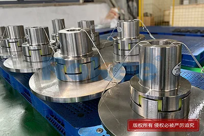
The core structural framework of plum couplings is composed of two independent metal coupling halves with identical structural specifications, which form the outer load-bearing and connecting part of the entire coupling structure. Observed from the structural diagram, each coupling half is processed with evenly distributed protruding claw teeth on the inner end face, and the claw teeth of the two halves are arranged in a staggered and meshed state after assembly, creating uniform embedded gaps for placing the intermediate elastic body. These metal coupling halves are usually forged or precision-machined from high-strength metal materials with good rigidity and wear resistance, ensuring that the coupling can withstand cyclic torque impact and maintain stable structural deformation during long-term continuous operation. The outer side of each coupling half is designed with a complete shaft sleeve structure with through holes, which can be tightly sleeved on the driving and driven shafts respectively, realizing the fixed connection between the coupling and the transmission shaft. The overall outline of the metal halves is smooth and regular, with no redundant protruding structures, forming a highly compact overall assembly space, which is one of the typical structural features distinguishing plum couplings from other elastic coupling types.
The plum-shaped elastic spacer is the most critical functional component in the structural diagram of plum couplings and the core medium for realizing flexible transmission and vibration buffering. Positioned in the staggered gaps between the claw teeth of the two metal coupling halves, this elastic component presents a regular multi-lobe plum blossom shape in the planar view of the structural diagram, with each lobe closely fitting the inner wall of the metal claw tooth gap. Made of high-elastic polymer materials with excellent toughness and fatigue resistance, this elastic spacer can produce uniform micro-deformation under torque load, avoiding rigid collision and hard friction between metal components. In the overall structural layout, the elastic spacer is in a fully clamped and limited state, with no relative displacement with the metal claw teeth during operation, ensuring continuous and stable torque transmission. The integrated one-piece structure of the elastic body eliminates the assembly gaps existing in multi-part elastic couplings, effectively reducing transmission vibration and noise. Meanwhile, the elastic body’s structural elasticity can offset tiny installation deviations and operation-induced shaft displacement, realizing automatic compensation for multi-directional shaft misalignment.
The assembly matching relationship shown in the structural diagram clearly reflects the internal force transmission path and structural coordination logic of plum couplings. After the two metal coupling halves are aligned and installed with the driving and driven shafts respectively, the staggered claw tooth structure forms a closed limit space for the central plum-shaped elastic body, and all power transmission processes are completed through the contact and deformation of the elastic body. When the equipment operates, the driving shaft drives the active coupling half to rotate, and the inner claw teeth of the active half apply uniform extrusion force on the lobe parts of the elastic spacer. The elastic body undergoes reversible elastic deformation under the extrusion force, and the stress is uniformly transmitted to the claw teeth of the driven coupling half, thereby driving the driven shaft to rotate synchronously and completing the power transmission cycle. The symmetrical structural design ensures that the stress on each lobe of the elastic body is consistent during operation, avoiding local overstress and premature wear. This indirect force transmission mode through elastic deformation fundamentally avoids rigid contact between metal parts, laying a structural foundation for the coupling’s shock absorption and noise reduction functions.
The structural diagram intuitively shows the multi-dimensional displacement compensation mechanism of plum couplings, which is an important structural advantage adapted to complex mechanical operation conditions. Benefiting from the elastic deformation performance of the central plum-shaped spacer and the reserved matching gaps in the assembly structure, the coupling can effectively compensate for three types of common shaft displacement in mechanical transmission systems. In terms of axial displacement, the elastic body can produce small tensile and compressive deformation along the shaft direction to adapt to the tiny axial expansion and contraction of the shaft caused by equipment operation and temperature changes. For radial displacement, the flexible fit between the elastic lobe and the metal claw tooth allows a certain range of radial offset of the two shafts without affecting normal power transmission. In terms of angular displacement, the elastic body’s uniform deformation can adapt to the minor angle deviation between the axes of the driving and driven shafts. The integrated elastic structure ensures that the compensation process is stable and smooth, without generating additional transmission resistance or vibration, effectively protecting the transmission shaft and related mechanical components from eccentric wear and impact damage.
The structural design details reflected in the plum coupling diagram determine its excellent operational stability and convenient maintenance characteristics. The overall assembly structure adopts a non-lubrication design, with all power transmission and buffer functions realized by the self-performance of the elastic body, eliminating the need for regular grease filling and lubrication maintenance required by gear couplings and other rigid transmission components. The modular assembly structure is simple and intuitive, with the metal coupling halves and elastic spacer forming an independent assembly unit, and the elastic body can be directly replaced without disassembling the connected shafts and metal halves when wear or aging occurs. The symmetrical and uniform claw tooth structure ensures balanced stress distribution during high-speed rotation, effectively reducing rotational inertia and centrifugal force, and avoiding equipment jitter and abnormal noise. In addition, the compact structural layout reduces the overall occupied space of the transmission part, which can adapt to mechanical equipment with limited installation space. These structural details make plum couplings have outstanding practicability and economy in industrial application scenarios.
The structural characteristics of plum couplings also endow them with unique performance boundaries and application adaptability, which can be clearly analyzed through the structural diagram. The flexible transmission structure dominated by the elastic spacer determines that the coupling has excellent buffering and damping effects, which can effectively absorb the instantaneous impact load generated by equipment start-stop, variable speed operation and load fluctuation, and protect motors, reducers and other precision transmission equipment from impact damage. Compared with diaphragm couplings, the plum coupling structure is simpler and more cost-effective in processing and assembly; compared with sleeve couplings, it has flexible compensation capabilities and better anti-vibration performance. However, limited by the material characteristics of the elastic body and the structural stress mode, it is more suitable for medium and low-speed, medium-load transmission scenarios, and is not applicable to ultra-high-speed and heavy-duty impact working conditions. The regular and symmetrical structural design also ensures good dynamic balance performance, enabling stable long-term operation of the equipment and reducing the failure rate of the transmission system.
In summary, the complete structural diagram of plum couplings systematically presents a scientific and efficient flexible transmission structure with simple composition, reasonable stress and complete functions. The collaborative matching of rigid metal framework and flexible elastic core forms the core structural logic of torque transmission, vibration damping and displacement compensation. Every structural detail from the staggered claw tooth layout of the coupling halves to the integrated plum-shaped elastic design is optimized for practical mechanical transmission needs, realizing the perfect balance between transmission efficiency and operation protection. With its compact structure, convenient maintenance, stable performance and strong adaptability, plum couplings have become indispensable basic components in general mechanical transmission systems. In subsequent structural optimization and application expansion, further improvement of coupling performance can be realized by adjusting elastic body structural parameters and optimizing metal structure matching, so as to adapt to more diversified mechanical operation scenarios.
Tags: Plum Blossom Couplings , Plum Couplings , Flexible Plum Blossom Coupling , sandwich panel machine , pu sandwich panel line
« Structural Diagram of Plum Couplings » Update Date: 2026/8/13
URL: https://www.rokee.com/en/blog/structural-diagram-of-plum-couplings.html
Contact
If you require custom machined couplings, please contact Rokee via the contact information below for inquiries.
Email: Rokee@Rokee.com
 WeChat