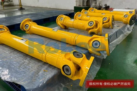
Working Principle of Cardan Driveshaft
The cardan driveshaft stands as a fundamental mechanical transmission component designed to transfer rotational torque and motion between two misaligned mechanical parts, serving as a flexible power connection core in various mobile and industrial mechanical systems. Its core operational logic relies on the structural coordination of universal joints and telescopic shaft segments, which effectively compensate for angular deviation, axial displacement and minor radial offset between driving and driven components during equipment operation. Unlike rigid transmission shafts that require precise coaxial alignment, the cardan driveshaft adapts to dynamic position changes of mechanical parts caused by vibration, displacement and structural movement. This article systematically elaborates on its internal structural composition, basic motion mechanism, torque transmission process, kinematic characteristics, dynamic compensation mode, operational stability factors and practical application adaptability, revealing the complete working principle behind its efficient and flexible power transmission performance in complex mechanical operating environments.

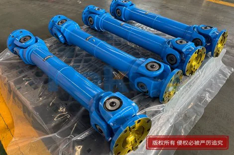
The basic structural composition of a cardan driveshaft lays the physical foundation for its unique working principle, with each component undertaking independent and coordinated transmission functions to ensure continuous and stable power output. The core components include universal joints installed at both ends, a middle transmission shaft body, telescopic spline mechanisms and auxiliary bearing assemblies. Each universal joint consists of two symmetrical yoke frames and a central cross spider, where the four shaft heads of the cross spider are hinged with the yokes through precision needle roller bearings. This hinged structure allows free rotational deflection in multiple spatial directions, breaking the transmission limitation of fixed-axis rotation of rigid shafts. The middle shaft body adopts a hollow or solid integrated structure to bear torsional load while reducing overall weight and rotational inertia. The telescopic spline mechanism, composed of inner and outer spline sleeves, realizes axial stretching and contracting movement, which can automatically adapt to the distance change between driving and driven ends during mechanical operation. All components are tightly matched and coordinated, forming a complete flexible transmission system that can respond to multi-dimensional position deviations in real time.
The core working mechanism of the cardan shaft originates from the spatial motion characteristics of the universal joint cross hinge structure, which realizes torque transmission under angular misalignment conditions. When the driving end mechanical part outputs rotational power, the driving yoke fixed on the input shaft starts synchronous rotation and drives the cross spider to perform circular motion around the central axis. Driven by the cross spider, the driven yoke and the connected output shaft rotate synchronously, completing the basic transmission of rotational torque. In this process, the needle roller bearings between the cross spider and yokes greatly reduce sliding friction during deflection and rotation, avoiding mechanical jamming and energy loss. The most distinctive feature of this mechanism is its adaptive angular deflection capability: when the input and output shafts produce a certain included angle due to mechanical vibration or structural displacement, the cross spider can adjust its spatial posture in real time to maintain continuous torque transmission without interrupting power output. This flexible hinged motion fundamentally solves the problem that traditional rigid transmission structures cannot adapt to angular misalignment operation.
The telescopic compensation principle of the cardan driveshaft complements the angular deflection function of universal joints, realizing full-dimensional adaptive transmission of power. In actual mechanical operation, the distance between the driving and driven ends often changes dynamically due to equipment vibration, structural deformation and working stroke adjustment. The spline telescopic structure embedded in the middle section of the driveshaft is responsible for absorbing such axial displacement changes. The inner spline shaft and outer spline sleeve are in precise meshing fit, which can slide relatively along the axial direction while maintaining synchronous rotational motion, ensuring that the transmission torque is not lost during stretching and contracting. The spline structure adopts uniform tooth profile design, which can evenly disperse torsional load and avoid local stress concentration caused by axial sliding. The coordination of telescopic axial compensation and universal joint angular deflection enables the cardan driveshaft to cope with composite displacement changes including angle deviation and distance fluctuation, greatly expanding the adaptable working conditions of mechanical power transmission and improving the environmental adaptability of transmission systems.
The kinematic characteristics of cardan driveshaft transmission include inherent non-uniform angular velocity transmission and its balanced optimization logic, which is a key feature of its working principle. When a single universal joint works with a deflection angle between input and output shafts, the angular velocity of the output shaft will produce periodic fluctuation, that is, the output rotational speed accelerates and decelerates alternately within a single rotation cycle, even if the input shaft maintains constant-speed rotation. This speed fluctuation is caused by the spatial motion track difference of the cross spider’s two groups of hinged ends. To eliminate the adverse impact of non-uniform velocity transmission on mechanical operation, most cardan driveshafts adopt a double universal joint symmetrical layout. By setting two universal joints with opposite deflection angles at both ends of the middle shaft body, the speed fluctuation generated by the first joint is completely offset by the second joint, realizing constant-speed and stable output of the final driven shaft. This kinematic balance design effectively avoids vibration, impact and component wear caused by speed fluctuation, ensuring the smooth operation of the entire transmission system.
The torque bearing and load transmission principle of the cardan driveshaft determines its durability and operational reliability under complex working loads. During operation, the driveshaft bears alternating torsional load, shear force and impact load generated by mechanical start, stop and variable-speed operation. The cross spider and bearing assembly of the universal joint are the main load-bearing parts, which convert the input torsional torque into spatial hinged driving force and transmit it stably to the output end. The needle roller bearing structure can bear large alternating torsional pressure while maintaining flexible rotation, and the uniform stress distribution of the cross structure avoids fracture and deformation under high load. The middle shaft body is designed with optimized torsional rigidity, which can resist torsional deformation during high-torque transmission and ensure the accuracy of rotational motion. When the mechanical load changes suddenly, the flexible coordination of the universal joint and spline structure can buffer instantaneous impact force, reduce rigid impact between mechanical components, and protect the driving and driven equipment from load impact damage, realizing safe and stable load transmission.
The dynamic stability maintenance principle runs through the entire operation process of the cardan driveshaft, ensuring long-term efficient transmission in variable working environments. In continuous operation, mechanical vibration and working temperature changes will cause minor structural deformation and position deviation of transmission components. The multi-degree-of-freedom flexible structure of the cardan driveshaft can automatically adapt to these subtle changes: the universal joint micro-deflection corrects angular deviation, and the spline telescopic structure compensates for axial deformation displacement, always maintaining the optimal transmission matching state. Meanwhile, the rotating inertia matching of the shaft body and the friction optimization of the bearing components reduce rotational resistance and abnormal vibration during operation. The symmetrical structural layout of the double universal joints ensures the dynamic balance of the rotating shaft body, avoiding eccentric rotation and resonance phenomena. This active adaptive stability adjustment enables the cardan driveshaft to maintain consistent transmission efficiency and operational stability under long-term variable load and variable displacement working conditions, reducing failure rates and maintenance costs.
The practical application adaptability of the cardan driveshaft is derived from the integration and optimization of all the above working principles, making it an indispensable transmission component in multiple mechanical fields. Its core advantages of multi-dimensional displacement compensation, stable torque transmission and dynamic load buffering enable it to adapt to power transmission scenarios where the relative position of mechanical components changes frequently. In mobile mechanical equipment, it can cope with the continuous position change of power components caused by walking and vibration; in industrial transmission equipment, it adapts to the structural displacement and load fluctuation of mechanical operation. Compared with other flexible transmission components, the cardan driveshaft combines high torque transmission capacity and large displacement compensation range, with simple and reliable structural logic and strong environmental adaptability. The perfect coordination of kinematic mechanism, load-bearing performance and dynamic stability ensures that it can maintain efficient and accurate power transmission in complex and changeable mechanical working environments, fully reflecting the unique mechanical value of its working principle design.
Tags: Cross Cardan Shafts , Industrial Cardan Shafts , Cardan Shafts , Cardan Shaft Couplings , Cardan Joint Drive Shafts , Cardan Driveshafts , Cardan Couplings , sandwich panel machine , pu sandwich panel line
« Working Principle of Cardan Driveshaft » Update Date: 2026/9/1
URL: https://www.rokee.com/en/blog/working-principle-of-cardan-driveshaft.html
Contact
If you require custom machined couplings, please contact Rokee via the contact information below for inquiries.
Email: Rokee@Rokee.com
 WeChat