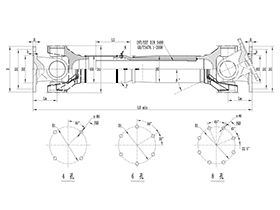
Universal Cross Joint Coupling Structural Diagram
Rokee® is a well-known high-quality universal cross joint coupling supplier from china, learn more about universal cross joint coupling structural diagram, pls contact Rokee technology. Rokee has been established in China since 1999, over the years, with excellent quality, we have been continuously providing many universal cross joint coupling products of various categories and uses complying with multiple standards and a full range of services, from the universal cross joint coupling selection to final installation and operation, for the industry fields of ferrous metallurgy, nuclear power, gas turbine, wind power, ropeway construction, lifting transportation, general equipment, etc.
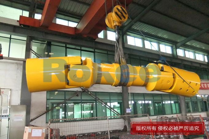
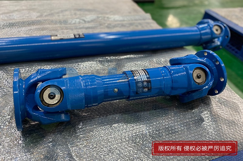
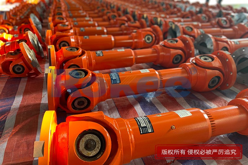
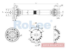
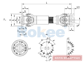
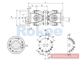
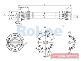
The universal cross joint coupling uses cross bearings to connect the flanges at both ends, which can transmit torque that is not on the same axis. The diagonal compensation can reach more than 25°, and the spline connection can compensate for the axial displacement in a large distance. With high carrying capacity and excellent transmission efficiency, universal cross joint coupling is widely used in modern industrial fields.
Universal Cross Joint Coupling Products
-
![ROWS-BH Cardan Shaft,Universal Cross Joint Coupling Structural Diagram]()
ROWS-BH Cardan Shaft
View More -
![ROWL-BH Cardan Shaft,Universal Cross Joint Coupling Structural Diagram]()
ROWL-BH Cardan Shaft
View More -
![ROWM-BH Cardan Shaft,Universal Cross Joint Coupling Structural Diagram]()
ROWM-BH Cardan Shaft
View More -
![ROWH-BH Cardan Shaft,Universal Cross Joint Coupling Structural Diagram]()
ROWH-BH Cardan Shaft
View More -
![ROWS-WD Cardan Shaft,Universal Cross Joint Coupling Structural Diagram]()
ROWS-WD Cardan Shaft
View More -
![ROWM-WD Cardan Shaft,Universal Cross Joint Coupling Structural Diagram]()
ROWM-WD Cardan Shaft
View More -
![ROWH-WD Cardan Shaft,Universal Cross Joint Coupling Structural Diagram]()
ROWH-WD Cardan Shaft
View More -
![ROWL-WD Cardan Shaft,Universal Cross Joint Coupling Structural Diagram]()
ROWL-WD Cardan Shaft
View More -
![ROWM-WH Cardan Shaft,Universal Cross Joint Coupling Structural Diagram]()
ROWM-WH Cardan Shaft
View More -
![ROWH-WH Cardan Shaft,Universal Cross Joint Coupling Structural Diagram]()
ROWH-WH Cardan Shaft
View More -
![ROWL-WH Cardan Shaft,Universal Cross Joint Coupling Structural Diagram]()
ROWL-WH Cardan Shaft
View More -
![ROWS-WH Cardan Shaft,Universal Cross Joint Coupling Structural Diagram]()
ROWS-WH Cardan Shaft
View More -
![SWC-BH Universal Coupling,Universal Cross Joint Coupling Structural Diagram]()
SWC-BH Universal Coupling
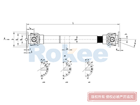
standard telescopic welded
View More -
![SWC-CH Uuniversal Coupling,Universal Cross Joint Coupling Structural Diagram]()
SWC-CH Uuniversal Coupling
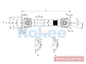
Long Telescopic Welded
View More -
![SWC-DH Universal Coupling,Universal Cross Joint Coupling Structural Diagram]()
SWC-DH Universal Coupling
Short Telescopic Welded
View More -
![SWC-WD Universal Coupling,Universal Cross Joint Coupling Structural Diagram]()
SWC-WD Universal Coupling
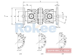
Non-telescopic Short
View More -
![SWC-WH Universal Coupling,Universal Cross Joint Coupling Structural Diagram]()
SWC-WH Universal Coupling
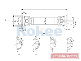
Non-telescopic Welded
View More -
![SWP-A Universal Coupling,Universal Cross Joint Coupling Structural Diagram]()
SWP-A Universal Coupling
Long Type, Telescopic
View More -
![SWP-B Universal Coupling,Universal Cross Joint Coupling Structural Diagram]()
SWP-B Universal Coupling
Short Type, Telescopic
View More -
![SWP-C Universal Coupling,Universal Cross Joint Coupling Structural Diagram]()
SWP-C Universal Coupling
Short Type, Non-telescopic
View More -
![SWP-D Universal Coupling,Universal Cross Joint Coupling Structural Diagram]()
SWP-D Universal Coupling
Long Type, Non-elescopic
View More

In the vast landscape of mechanical power transmission systems, the universal cross joint coupling stands as a timeless and indispensable component, bridging the gap between misaligned rotating shafts and enabling seamless torque transfer across diverse industrial and mechanical setups. Unlike rigid couplings that demand perfect shaft alignment, this specialized coupling is engineered to accommodate angular misalignment between input and output shafts, a common challenge in real-world machinery where thermal expansion, mechanical vibration, assembly tolerances, and dynamic operational shifts disrupt perfect collinearity. The structural design of the universal cross joint coupling is a masterclass in mechanical simplicity and functional efficiency, with every component working in tandem to deliver reliable performance under varying loads and angular offsets. By dissecting its structural diagram, understanding its core operating principles, analyzing its mechanical characteristics, and exploring its wide-ranging applications, we can fully grasp the pivotal role this component plays in modern mechanical engineering, as well as the engineering logic that underpins its enduring relevance across countless systems.
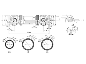
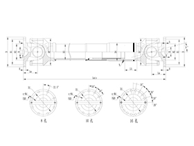
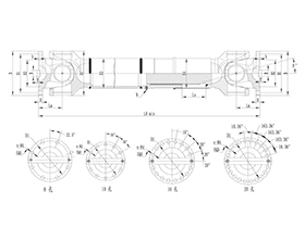
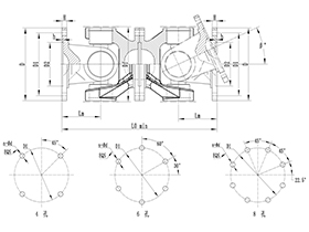
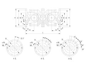
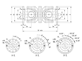
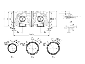
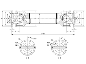
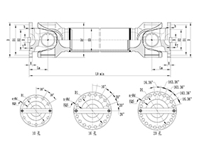
At the heart of the universal cross joint coupling lies a straightforward yet robust structural configuration, centered around a cross-shaped core component known as the cross shaft or spider, which serves as the pivotal link between two shaft-mounted yokes. A standard universal cross joint coupling consists of four primary structural elements: the driving yoke, the driven yoke, the cross shaft, and precision bearing assemblies, with additional sealing and lubrication components to enhance durability and operational stability. The driving yoke is firmly attached to the input shaft, which receives rotational power from a prime mover such as an engine, motor, or gearbox, while the driven yoke is secured to the output shaft that delivers power to the driven machinery. Both yokes feature a fork-like design, with open recesses machined to precisely house the opposing journals of the cross shaft, creating a articulated connection that allows for free angular movement. The cross shaft, the defining feature of this coupling, is a rigid, cross-shaped metal component with four cylindrical journals arranged perpendicularly to one another, two aligned with the driving yoke and two with the driven yoke, forming a 90-degree angular offset between the two sets of journals. This orthogonal arrangement is the key to the coupling’s ability to transmit rotation even when the connected shafts are at an angle to each other, as it allows each yoke to pivot independently around its respective set of cross shaft journals.
Surrounding each journal of the cross shaft are precision bearing assemblies, most commonly needle roller bearings, which are integral to the coupling’s smooth operation and load-bearing capacity. Needle roller bearings are selected for their compact design, high radial load capacity, and low friction characteristics, making them ideal for the confined space within the yoke recesses and the high rotational speeds typical of power transmission systems. These bearings eliminate direct metal-to-metal contact between the cross shaft journals and the inner surfaces of the yoke forks, reducing wear, minimizing frictional heat generation, and ensuring that angular movement and torque transmission occur with minimal energy loss. Complementing the bearing assemblies are sealing components, typically lip seals or dust caps, positioned at the interface between the yokes and the cross shaft journals. These seals serve two critical functions: retaining lubricating grease within the bearing cavities to maintain consistent lubrication and prevent dry friction, and blocking the ingress of external contaminants such as dust, moisture, dirt, and debris that could cause abrasive wear or corrosion to the bearings and cross shaft. The structural diagram of the universal cross joint coupling clearly illustrates this cohesive assembly, with all parts aligned symmetrically around the central axis of the cross shaft, emphasizing the balance and symmetry that define its mechanical behavior.
The operating principle of the universal cross joint coupling is derived directly from its structural design, relying on the articulated motion of the cross shaft to transfer rotational torque and motion between angled shafts. When the input shaft rotates, the driving yoke rotates in unison, transferring torque to the adjacent pair of cross shaft journals via the needle roller bearings. This rotational force causes the cross shaft to pivot around the axis of these journals, while the perpendicular pair of journals on the cross shaft transfer the motion and torque to the driven yoke and, in turn, the output shaft. Throughout this process, the cross shaft acts as a flexible intermediary, adjusting its angular position continuously to compensate for the misalignment between the driving and driven shafts. Unlike rigid couplings that lock shafts in a fixed position, the universal cross joint coupling allows the two shafts to maintain a consistent angular offset—typically ranging from 0 degrees up to 15 degrees for standard single joint models, with some heavy-duty variants accommodating larger angles—while sustaining uninterrupted power transmission. This adaptive motion is what makes the coupling so versatile, as it can handle both static misalignment present during assembly and dynamic shifts that occur during operation, such as those caused by suspension movement in automotive systems or machine vibration in industrial equipment.
While the single universal cross joint coupling excels at angular misalignment compensation, it exhibits an inherent mechanical characteristic known as non-uniform rotational velocity, a trait that shapes its application and installation requirements. When the driving shaft rotates at a constant speed, the driven shaft does not rotate at a perfectly uniform instantaneous speed; instead, its rotational velocity fluctuates periodically throughout each full rotation cycle. This velocity variation is a direct result of the geometric relationship between the cross shaft, yokes, and angled shafts, as the effective lever arm and rotational radius change continuously as the coupling turns. The magnitude of this velocity fluctuation is directly proportional to the angle between the driving and driven shafts—larger angular offsets lead to more pronounced speed variations, which can generate torsional vibration, increased noise, and accelerated wear on connected components if left unaddressed. In applications where smooth, constant-speed rotation is critical, engineers mitigate this issue by using a double universal cross joint coupling configuration, which pairs two single joints with an intermediate shaft. For this setup to deliver near-uniform velocity transmission, two key installation conditions must be met: the driving and driven shafts must form equal angles with the intermediate shaft, and the yokes at both ends of the intermediate shaft must be aligned in the same plane. When these conditions are satisfied, the velocity fluctuations of the first joint are counteracted by the opposing fluctuations of the second joint, resulting in smooth, consistent power delivery from input to output shaft.
The material selection for the universal cross joint coupling is a critical aspect of its structural integrity and performance, tailored to withstand the mechanical stresses of torque transmission, angular pivoting, and operational loads. The cross shaft and yokes are typically forged from high-strength alloy steel, chosen for its exceptional tensile strength, toughness, wear resistance, and ability to withstand repeated cyclic loading and impact forces. Forged alloy steel undergoes heat treatment processes such as quenching and tempering to enhance its mechanical properties, ensuring the components can handle heavy torque loads without deformation, cracking, or premature failure. The needle roller bearings are manufactured from high-carbon chromium steel, a material renowned for its hardness, dimensional stability, and wear resistance, which is essential for maintaining bearing precision and longevity under high-speed rotation and heavy radial loads. Sealing components are usually made from durable elastomers that resist degradation from oil, grease, temperature fluctuations, and environmental exposure, preserving the integrity of the lubrication system and protecting internal parts. This careful material pairing ensures the coupling can operate reliably in diverse operating environments, from moderate-temperature indoor machinery to harsh outdoor settings with extreme temperatures, moisture, and particulate matter.
Beyond its core structural and functional traits, the universal cross joint coupling offers a host of practical advantages that solidify its status as a staple in mechanical power transmission. Its compact and lightweight design allows for easy integration into space-constrained mechanical systems, making it suitable for applications where installation volume is limited. The coupling exhibits high transmission efficiency, with minimal energy loss due to friction, thanks to the precision needle roller bearings and optimized component tolerances, contributing to overall system energy efficiency. It is also highly adaptable, capable of handling both clockwise and counterclockwise rotation without performance degradation, and can accommodate small amounts of axial shaft movement in addition to angular misalignment, further enhancing its flexibility. Maintenance requirements are relatively straightforward, primarily involving periodic lubrication to replenish grease in the bearing cavities and routine inspections to check for wear, seal damage, or loose fasteners. When properly maintained, the universal cross joint coupling delivers a long service life, even under continuous heavy-duty operation, making it a cost-effective solution for long-term mechanical system performance.
The versatility of the universal cross joint coupling is reflected in its extensive use across a multitude of industries and mechanical applications, where shaft misalignment is a persistent challenge. In the automotive industry, it is a core component of drive shaft assemblies, connecting the transmission output shaft to the differential input shaft in rear-wheel-drive and four-wheel-drive vehicles. Here, it compensates for the vertical movement of the rear axle caused by road irregularities and suspension travel, ensuring consistent power delivery to the wheels regardless of vehicle load or terrain. In heavy machinery and construction equipment, such as excavators, loaders, cranes, and bulldozers, the coupling transmits high torque between engine and hydraulic systems, or between gearboxes and working attachments, enduring heavy impact loads and constant angular shifts in rugged working conditions. Industrial manufacturing machinery, including conveyor systems, milling machines, drilling equipment, and textile machinery, relies on the coupling to connect misaligned shafts, maintaining smooth operation and minimizing downtime caused by alignment issues. It also finds widespread use in agricultural machinery, marine propulsion systems, aerospace equipment, and various power transmission test rigs, adapting to the unique operational demands of each sector with its reliable misalignment compensation and torque transfer capabilities.
When integrating the universal cross joint coupling into a mechanical system, careful consideration must be given to installation, alignment, and operational parameters to maximize performance and service life. Proper alignment of the driving and driven shafts, even within the coupling’s misalignment tolerance, reduces unnecessary stress on components and minimizes velocity fluctuations and vibration. Torque ratings must be matched to the system’s operational load requirements; selecting a coupling with insufficient torque capacity can lead to premature failure, while an oversized coupling may add unnecessary weight and bulk to the system. Operating speed is another key factor, as high rotational speeds amplify the effects of any imbalance or misalignment, requiring tighter installation tolerances and more frequent maintenance. Additionally, environmental conditions such as extreme temperatures, corrosive substances, or high levels of dust may necessitate specialized coatings, sealed bearing designs, or enhanced lubrication protocols to protect the coupling from accelerated wear and damage. Adhering to these engineering best practices ensures the coupling operates at peak efficiency, supporting the overall reliability and functionality of the entire mechanical system.
As mechanical engineering continues to evolve with advancements in materials science, manufacturing technology, and system design, the universal cross joint coupling remains a foundational component, adapting to modern industry demands while retaining its core structural and functional principles. Modern manufacturing techniques, such as precision forging, CNC machining, and automated quality control, have refined the production of coupling components, improving dimensional accuracy, surface finish, and component consistency, which in turn enhances performance and reduces friction. Advanced materials, including high-performance alloy steels and wear-resistant coatings, have boosted the coupling’s load-bearing capacity and durability, allowing it to operate in more demanding industrial environments. Computational engineering tools have also enabled more precise analysis of the coupling’s mechanical behavior, allowing engineers to optimize designs for specific applications, minimize velocity fluctuations, and enhance overall system integration. Despite these advancements, the fundamental structural diagram of the universal cross joint coupling remains unchanged, a testament to the timeless efficiency of its design and its ability to meet the evolving needs of mechanical power transmission.
In summary, the universal cross joint coupling is a quintessential example of mechanical engineering ingenuity, combining a simple structural design with exceptional functional versatility to solve the pervasive challenge of shaft misalignment in power transmission systems. Its core structure—comprising two yokes, a cross shaft, precision bearings, and sealing components—works in harmony to deliver reliable torque transfer, while its adaptive operating principle accommodates both static and dynamic angular offsets. From automotive drivetrains to heavy industrial machinery, its widespread applications underscore its critical role in keeping mechanical systems running smoothly and efficiently. By understanding the structural details, operating principles, mechanical characteristics, and practical considerations of the universal cross joint coupling, engineers and technicians can make informed decisions about component selection, installation, and maintenance, ensuring optimal performance and longevity of the systems they design and service. As a cornerstone of mechanical power transmission, the universal cross joint coupling continues to prove that effective engineering solutions often lie in simplicity, durability, and adaptability, remaining an essential component in the ever-expanding world of mechanical engineering.
« Universal Cross Joint Coupling Structural Diagram » Update Date: 2026/3/7
URL: http://www.rokee.com/en/blog/universal-cross-joint-coupling-structural-diagram.html
Tags: Universal Cross Joint Couplings , sandwich panel machine