Cardan Shaft Alignment Tolerances
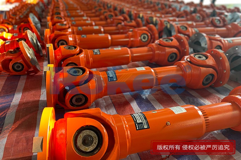
Rokee® is a well-known high-quality cardan shaft supplier from china, learn more about cardan shaft alignment tolerances, pls contact Rokee technology. Rokee has been established in China since 1999, over the years, with excellent quality, we have been continuously providing many cardan shaft products of various categories and uses complying with multiple standards and a full range of services, from the cardan shaft selection to final installation and operation, for the industry fields of ferrous metallurgy, nuclear power, gas turbine, wind power, ropeway construction, lifting transportation, general equipment, etc.
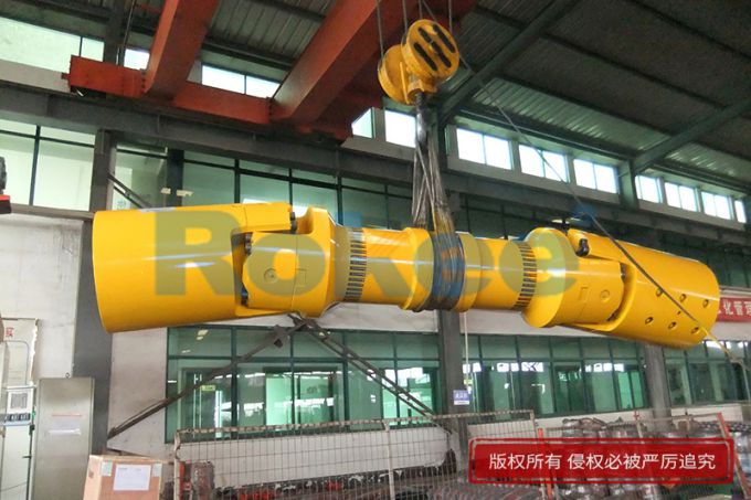
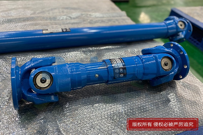
The cardan shaft uses cross bearings to connect the flanges at both ends, which can transmit torque that is not on the same axis. The diagonal compensation can reach more than 25°, and the spline connection can compensate for the axial displacement in a large distance. With high carrying capacity and excellent transmission efficiency, cardan shaft is widely used in modern industrial fields.
Cardan Shaft Products
-
![ROWS-BH Cardan Shaft,Cardan Shaft Alignment Tolerances]()
ROWS-BH Cardan Shaft
View More -
![ROWL-BH Cardan Shaft,Cardan Shaft Alignment Tolerances]()
ROWL-BH Cardan Shaft
View More -
![ROWM-BH Cardan Shaft,Cardan Shaft Alignment Tolerances]()
ROWM-BH Cardan Shaft
View More -
![ROWH-BH Cardan Shaft,Cardan Shaft Alignment Tolerances]()
ROWH-BH Cardan Shaft
View More -
![ROWS-WD Cardan Shaft,Cardan Shaft Alignment Tolerances]()
ROWS-WD Cardan Shaft
View More -
![ROWM-WD Cardan Shaft,Cardan Shaft Alignment Tolerances]()
ROWM-WD Cardan Shaft
View More -
![ROWH-WD Cardan Shaft,Cardan Shaft Alignment Tolerances]()
ROWH-WD Cardan Shaft
View More -
![ROWL-WD Cardan Shaft,Cardan Shaft Alignment Tolerances]()
ROWL-WD Cardan Shaft
View More -
![ROWM-WH Cardan Shaft,Cardan Shaft Alignment Tolerances]()
ROWM-WH Cardan Shaft
View More -
![ROWH-WH Cardan Shaft,Cardan Shaft Alignment Tolerances]()
ROWH-WH Cardan Shaft
View More -
![ROWL-WH Cardan Shaft,Cardan Shaft Alignment Tolerances]()
ROWL-WH Cardan Shaft
View More -
![ROWS-WH Cardan Shaft,Cardan Shaft Alignment Tolerances]()
ROWS-WH Cardan Shaft
View More -
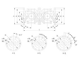
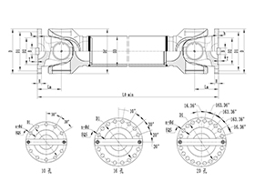
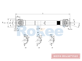
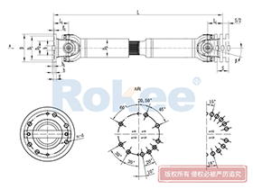
![SWC-BH Universal Coupling,Cardan Shaft Alignment Tolerances]()
SWC-BH Universal Coupling
standard telescopic welded
View More -
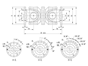
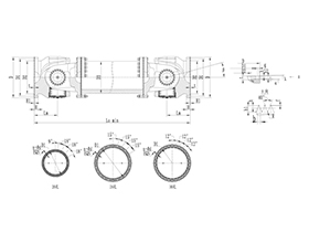
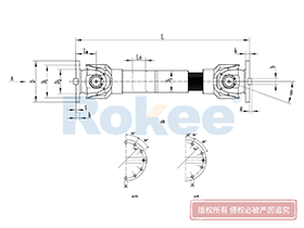
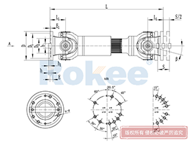
![SWC-CH Uuniversal Coupling,Cardan Shaft Alignment Tolerances]()
SWC-CH Uuniversal Coupling
Long Telescopic Welded
View More -
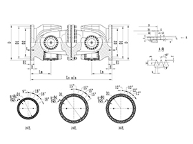
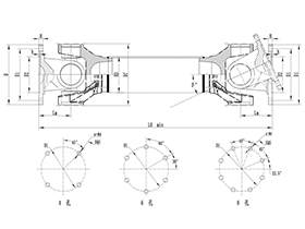
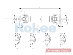
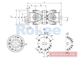
![SWC-DH Universal Coupling,Cardan Shaft Alignment Tolerances]()
SWC-DH Universal Coupling
Short Telescopic Welded
View More -
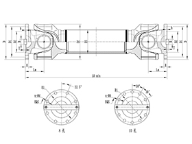
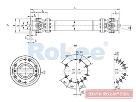
![SWC-WD Universal Coupling,Cardan Shaft Alignment Tolerances]()
SWC-WD Universal Coupling
Non-telescopic Short
View More -
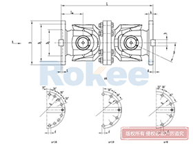
![SWC-WH Universal Coupling,Cardan Shaft Alignment Tolerances]()
SWC-WH Universal Coupling
Non-telescopic Welded
View More -
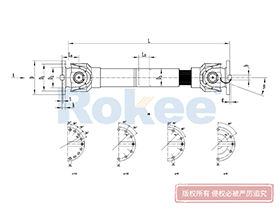
![SWP-A Universal Coupling,Cardan Shaft Alignment Tolerances]()
SWP-A Universal Coupling
Long Type, Telescopic
View More -
![SWP-B Universal Coupling,Cardan Shaft Alignment Tolerances]()
SWP-B Universal Coupling
Short Type, Telescopic
View More -
![SWP-C Universal Coupling,Cardan Shaft Alignment Tolerances]()
SWP-C Universal Coupling
Short Type, Non-telescopic
View More -
![SWP-D Universal Coupling,Cardan Shaft Alignment Tolerances]()
SWP-D Universal Coupling
Long Type, Non-elescopic
View More

In the landscape of mechanical power transmission, cardan shafts—commonly referred to as universal joint shafts—serve as indispensable components that bridge the gap between driving and driven machinery, enabling torque transfer even when shaft axes are not perfectly collinear. Unlike rigid coupling systems that demand strict axial alignment, cardan shafts offer a degree of flexibility to accommodate minor positional deviations, yet this adaptability is not boundless. The concept of alignment tolerances stands as the cornerstone of reliable cardan shaft operation, defining the acceptable limits of angular, radial, and axial misalignment that prevent premature wear, excessive vibration, energy loss, and catastrophic component failure. Mastering these tolerances, understanding their underlying mechanical principles, and applying them consistently during installation, commissioning, and routine maintenance are critical steps to uphold the efficiency, durability, and operational stability of entire drive systems across diverse industrial applications.
To grasp the significance of cardan shaft alignment tolerances, it is first necessary to dissect the core types of misalignment that these shafts encounter in real-world operating conditions. Broadly speaking, misalignment in cardan shaft assemblies falls into three distinct categories: angular misalignment, radial (parallel) misalignment, and axial displacement. Angular misalignment occurs when the central axes of the driving shaft, cardan shaft, and driven shaft intersect at an angle rather than remaining perfectly parallel, creating uneven stress distribution across the universal joint bearings and cross assemblies. Radial misalignment, by contrast, involves a lateral offset between the central axes of the connected shafts, with no angular deviation, which places additional shear stress on the joint components and alters the natural rotational dynamics of the shaft system. Axial displacement refers to the forward or backward movement of the shafts along their central axes, a factor that, while often less critical than angular or radial misalignment, must still be controlled within defined limits to avoid binding, excessive end play, or compromised lubrication within the joint assemblies. Each type of misalignment interacts with the others in practical setups, meaning alignment tolerances must address combined deviations rather than isolated issues, adding layers of complexity to the alignment process.
Angular alignment tolerances are arguably the most critical parameters for cardan shaft performance, as even small deviations from the optimal angular range can trigger severe operational issues. The fundamental design of universal joints means that non-uniform rotational velocity is inherent when operating at an angle; a single universal joint will cause the driven shaft to accelerate and decelerate twice per full rotation relative to the driving shaft, a phenomenon that generates cyclic vibration and dynamic loading. To mitigate this effect, dual universal joint cardan shafts are engineered with a specific phase alignment and geometric configuration—typically Z or W arrangement—to balance velocity fluctuations and achieve near-uniform rotation. This balancing act hinges entirely on maintaining equal angular misalignment at both end joints of the cardan shaft, a requirement that forms the basis of angular tolerance standards. In most industrial scenarios, the maximum permissible angular misalignment at each universal joint is capped at a modest threshold to prevent excessive stress, with allowable angles varying based on shaft size, operating speed, torque load, and intended service life. Higher rotational speeds and heavier torque loads demand tighter angular tolerances, as the dynamic forces amplified by speed magnify the impact of even minor angular errors. Operating beyond the recommended angular tolerance not only accelerates wear on bearing surfaces, cross pins, and yoke assemblies but also induces resonant vibration that can spread to adjacent machinery, damaging bearings, gears, and structural supports over time.
Radial alignment tolerances, while often overshadowed by angular constraints, play a vital role in preserving the long-term integrity of cardan shaft systems. Unlike flexible couplings designed specifically to handle large parallel offsets, cardan shafts are optimized to manage angular misalignment and moderate radial deviations, making strict radial tolerance control essential. Excessive radial offset disrupts the uniform distribution of load across the universal joint bearings, creating localized high-stress zones that lead to premature fatigue and failure. The acceptable radial tolerance for a cardan shaft assembly is closely tied to the shaft’s length, diameter, and operating speed; longer, narrower shafts typically require tighter radial tolerances to avoid lateral deflection and vibration, while shorter, heavier shafts can accommodate slightly larger offsets within reason. During alignment, technicians must ensure that radial misalignment is confined to either the vertical or horizontal plane, as combined multi-plane radial deviation complicates correction and increases the risk of unbalanced loading. Even when radial misalignment falls within the stated tolerance range, it is crucial to verify that the offset does not create additional angular deviation, as the two forms of misalignment often compound each other to push the assembly outside acceptable operating limits. Regular measurement of radial runout during operation can also provide early warning of shifting alignment, allowing for corrective action before minor deviations escalate into major mechanical problems.
Axial alignment tolerances, though less restrictive than angular and radial parameters, are not to be overlooked in the quest for optimal cardan shaft performance. Cardan shafts often incorporate splined sections to accommodate minor axial movement, a design feature that compensates for thermal expansion, mechanical settling, and minor positional shifts during operation. However, this axial flexibility has clear limits, and exceeding the prescribed axial tolerance can lead to a host of issues, including insufficient spline engagement, lubricant leakage, increased backlash, and even complete disengagement of shaft components under load. The acceptable axial displacement for a cardan shaft is determined by the length of the splined section, the design of the locking mechanisms, and the thermal characteristics of the operating environment. In high-temperature applications, for example, axial tolerances must account for predictable thermal expansion to prevent binding or excessive end play, while in cold environments, tighter axial controls may be necessary to maintain proper spline meshing. During installation, technicians must set axial positioning to the midpoint of the allowable tolerance range whenever possible, providing a buffer for both operational movement and thermal changes. Neglecting axial tolerance guidelines can lead to sudden mechanical failures, particularly in heavy-duty applications where sudden load changes or temperature fluctuations are common, highlighting the need for holistic alignment that addresses all three misalignment types simultaneously.
Translating alignment tolerance guidelines into practical, consistent results requires a structured approach to measurement and adjustment, as well as an understanding of the factors that can compromise alignment accuracy over time. Traditional alignment methods rely on mechanical measuring tools such as dial indicators, straightedges, and feeler gauges, which can deliver sufficient accuracy for low-speed, light-load applications when used with precision. For high-speed, heavy-duty, or precision-critical systems, advanced optical and laser alignment tools have become standard, offering higher precision, faster measurement, and the ability to assess combined misalignment in real time. Regardless of the measurement method, the alignment process follows a consistent workflow: initial inspection of shaft and joint condition, rough positioning to bring misalignment within the general tolerance range, incremental fine-tuning to meet precise tolerance specifications, and post-adjustment verification to confirm compliance. It is important to note that alignment is not a one-time task; machinery settling, thermal cycling, vibration-induced shifting, and routine wear can all cause alignment to drift outside acceptable tolerances during regular operation. Scheduled alignment checks, integrated into routine maintenance protocols, are essential to catch minor deviations early, preventing the gradual degradation of performance and avoiding costly unplanned downtime.
The impact of adhering to—or deviating from—cardan shaft alignment tolerances extends far beyond the shaft itself, influencing overall system efficiency, maintenance costs, and operational safety. When alignment is maintained within the prescribed tolerances, cardan shafts operate with minimal vibration, reduced friction, and balanced load distribution, maximizing power transmission efficiency and extending the service life of joints, bearings, and associated machinery. This translates to lower energy consumption, fewer replacement parts, and reduced labor hours spent on reactive repairs. Conversely, operating outside of alignment tolerances creates a cascade of negative effects: increased friction elevates energy usage and heat generation, accelerating the breakdown of lubricants and causing premature wear of critical components; excessive vibration damages not only the cardan shaft but also connected gearboxes, motors, and driven equipment; and unbalanced loading can lead to sudden, catastrophic failure such as shaft breakage or joint separation, posing safety risks to personnel and causing extensive damage to production equipment. In industrial settings where downtime carries significant financial costs, the investment in precise alignment and strict tolerance adherence is a proactive measure that delivers substantial long-term returns, enhancing both operational reliability and bottom-line profitability.
Beyond installation and maintenance, alignment tolerance considerations also shape the design and selection of cardan shafts for specific applications. Engineers must evaluate the operating conditions—including speed, torque, temperature, and expected positional shifts—to select a cardan shaft with tolerance ranges that match the application’s demands, rather than adopting a one-size-fits-all approach. Shafts designed for heavy industrial machinery, such as mining equipment or marine propulsion systems, feature more robust construction and tighter alignment tolerances to withstand extreme loads and harsh environments, while shafts used in light-duty conveyors or auxiliary equipment may have slightly more flexible tolerance parameters. Additionally, the length and configuration of the cardan shaft directly impact alignment feasibility; longer shafts require tighter tolerances to counteract lateral deflection, while compact shafts offer greater tolerance to minor misalignment. Collaboration between design engineers, installation technicians, and maintenance personnel is key to ensuring that alignment tolerance requirements are embedded into every stage of the cardan shaft lifecycle, from initial selection to end-of-service replacement.
Training and technical competence also play a pivotal role in maintaining cardan shaft alignment tolerances, as even the most precise tools and clear guidelines are ineffective without skilled personnel to implement them. Technicians responsible for alignment must understand the mechanical principles of universal joint operation, the specific tolerance requirements for different shaft types and applications, and the proper use of measurement tools to avoid human error. Ongoing training to refresh knowledge of best practices, emerging alignment techniques, and tolerance updates ensures that alignment work remains consistent and accurate, reducing the risk of misalignment due to procedural mistakes. Documenting alignment measurements, adjustments, and tolerance compliance for each cardan shaft assembly also creates a valuable historical record, enabling trend analysis to predict potential alignment issues and optimize maintenance schedules. This combination of skilled execution, rigorous documentation, and proactive monitoring forms a comprehensive framework for sustaining alignment integrity and maximizing the performance of cardan shaft systems.
In summary, cardan shaft alignment tolerances are not arbitrary technical specifications but critical parameters that govern the reliability, efficiency, and safety of mechanical drive systems. The interplay of angular, radial, and axial misalignment requires a holistic approach to alignment, with tight control of each parameter within defined limits to prevent operational issues and premature failure. From the initial design and selection of cardan shafts to precise installation, ongoing maintenance, and regular alignment verification, strict adherence to tolerance guidelines is a continuous process that demands attention to detail, technical skill, and proactive planning. By prioritizing alignment accuracy and respecting the established tolerance boundaries, operators and maintenance teams can unlock the full potential of cardan shafts, ensuring smooth, efficient power transmission, minimizing maintenance costs, and extending the operational life of critical industrial equipment. In an era where industrial efficiency and reliability are paramount, the mastery of cardan shaft alignment tolerances remains a fundamental pillar of effective mechanical engineering and equipment management.
« Cardan Shaft Alignment Tolerances » Update Date: 2026/3/7
URL: http://www.rokee.com/en/blog/cardan-shaft-alignment-tolerances.html
Tags: Cross Cardan Shafts , Industrial Cardan Shafts , Cardan Shafts , Cardan Shaft Couplings , sandwich panel machine